
Diesel conversion to pneumatic engine zero emissions and fuel cost

a technology of pneumatic engine and conversion method, which is applied in the direction of machines/engines, electric/magnetic/electromagnetic heating, electric generator control, etc., can solve the problems of natural phenomenon uncontrolled violent reaction, no prior art device example found, etc., and achieve zero harmful emissions, zero recurring fuel cost, and light weight and quiet

Inactive Publication Date: 2008-06-05
BAILEY RUDOLPH V
View PDF10 Cites 8 Cited by
  • Summary
  • Abstract
  • Description
  • Claims
  • Application Information

AI Technical Summary

Benefits of technology

[0004]The present version of the invention, which will be described in greater detail hereinafter, relates to the field of devices that can convert the conventional diesel engine to a pneumatic engine with zero harmful emissions, and zero recurring fuel cost. More specifically, this version of the invention is concerned with an engine conversion package employing a 3-way-valve locomotive type dual action high pressure high CFM compressed-air pump, designed for a new use, to convert the diesel engine to a pneumatic engine. The said air-pump is designed to be light weight and quiet and can deliver above 500 to 1500 PSI, and CFM capable to operate the desired engines, instead of diesel fuel. The invention includes other novel aspects that will be described in detail hereinafter.
[0021]A final but very significant advantage of our version of the invention is to provide a Diesel to Pneumatic Engine Conversion Package that will help to rid the planet form green-house gas emissions and from global warming and its projected catastrophic consequences.

Problems solved by technology

No example has been found of a prior art device which perform the specified functions of converting the conventional diesel engine to a non-fuel-burning pneumatic engine.
The original definition stated: “When air or gasses of varying temperature, volume, pressure, and velocity are suddenly mixed under certain conditions, they can cause a natural phenomenon uncontrolled violent reaction.

Method used


Image

  • Diesel conversion to pneumatic engine zero emissions and fuel cost
  • Diesel conversion to pneumatic engine zero emissions and fuel cost
  • Diesel conversion to pneumatic engine zero emissions and fuel cost

Examples


Embodiment Construction

Description

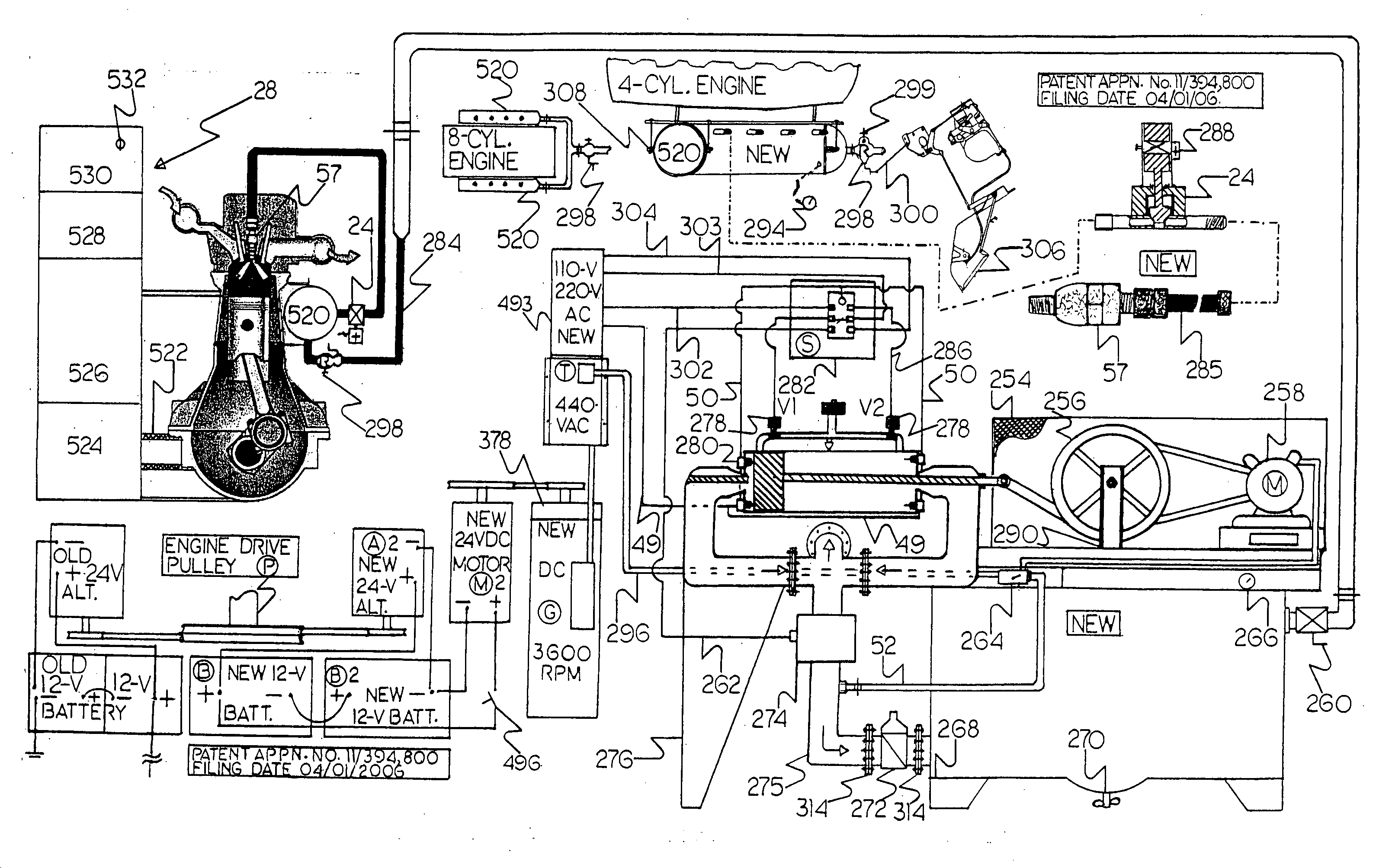
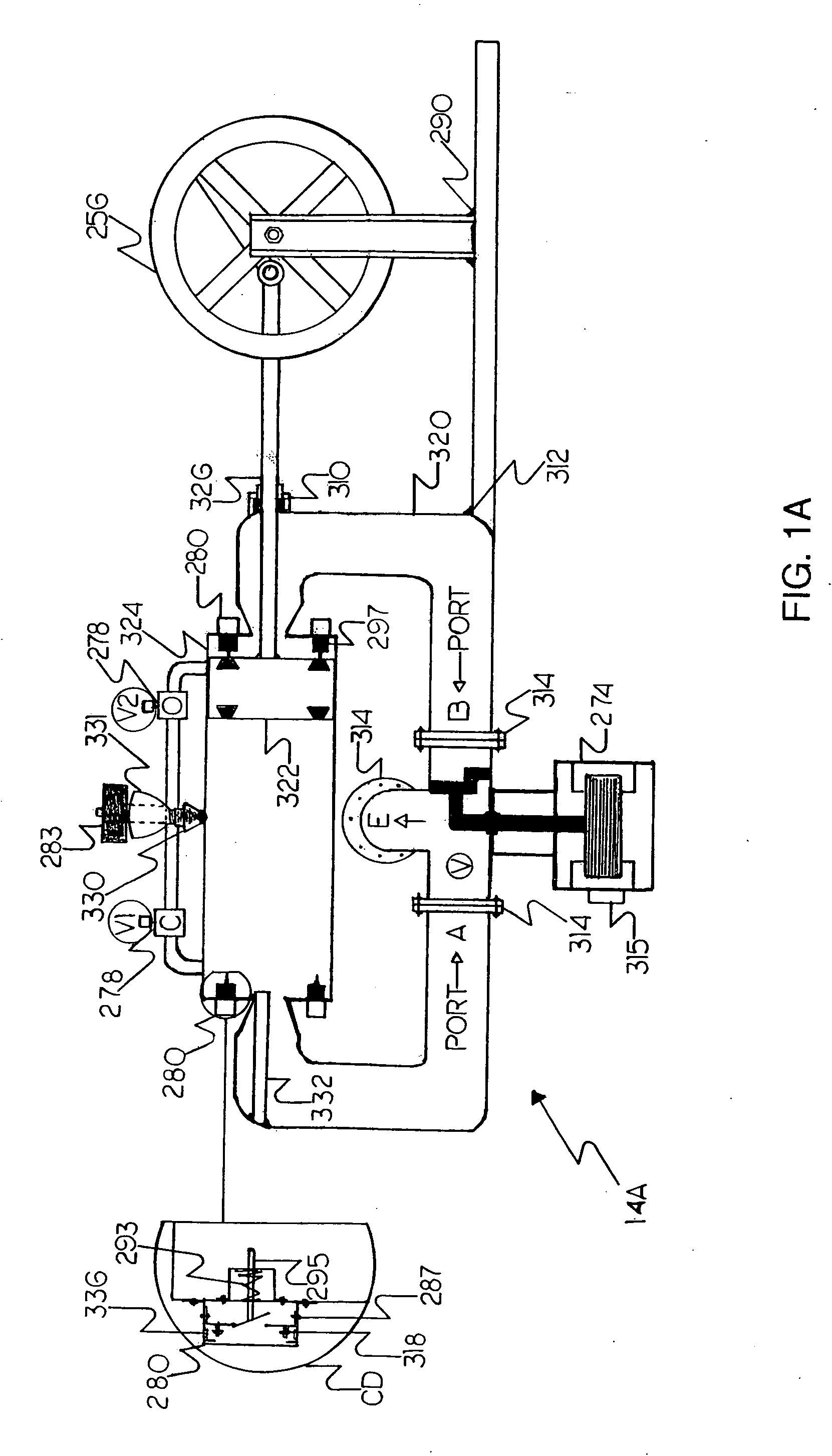
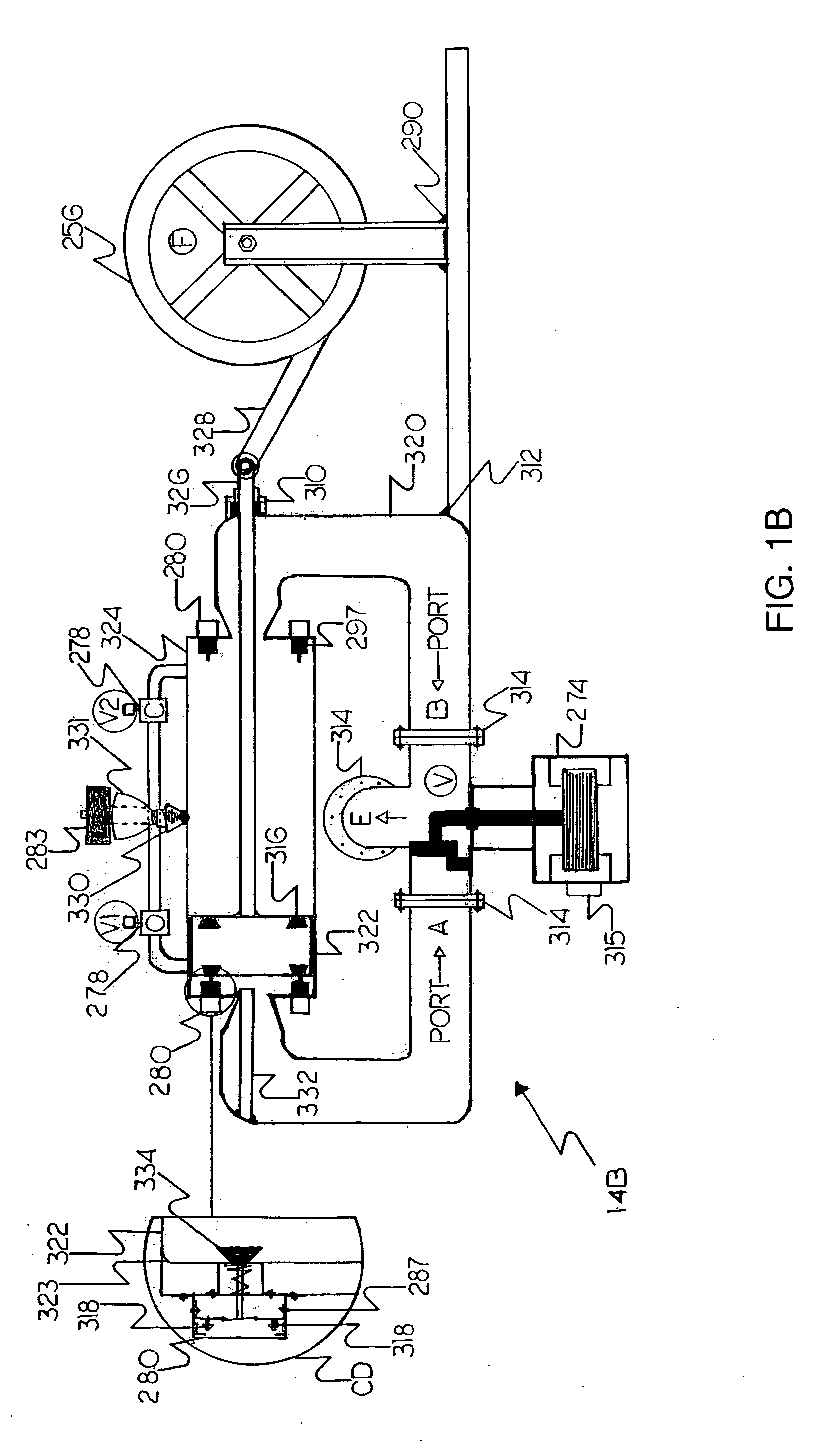
[0131]Referring now to the drawings and in particular, to FIG. 1A wherein there is illustrated a typical embodiment of a dual-action 3-way-valve locomotive type high pressure and CFM compressed-air pump 14A. The present version of the invention 14A is designed for a new use to convert the conventional diesel engine to a pneumatic engine, with zero harmful emissions and zero recurring fuel cost. The present version of the invention 14A is constructed of materials and components that are lightweight, quiet, durable, and resistant to corrosion and oxidization, such as rudder, plastic, aluminum, carbon steel, or stainless steel, various composite materials or a combination thereof. The device 14A consist of a steel high pressure air-pump cylindrical section 324 machined to mate with a steel high pressure air-pump plunger 322. High pressure steel pipe 320 is connected to each end of cylinder 324 as illustrated, with reducing cone ends. Air-plunger-shaft 326 is connected to fly...


PUM


Abstract

A method of converting a diesel engine to a fuel-free and pollution-free pneumatic engine has been disclosed. A conventional diesel engine can be converted to a non-fuel-burning emission-free pneumatic engine. This can be accomplished by using the engine to operate a DC inverted to AC generator and using the AC current to operate a compressed-air device capable of delivering over 500 PSI and CFM enough to operate the engine in place of diesel fuel. Since the diesel engine compresses air to temperatures of about 1000 degrees F. and pressures of about 500 PSI, if one mixes it with cold air at pressures above 500 PSI a violent reaction will occur which will drive the engine piston downwards with force enough that when repeated in accordance with the engine's firing order it will cause the vehicle to self-propel along a surface.

Description

DESCRIPTION OF RELATED APPLICATIONS[0001]This application is a continuation-in-part of CO-pending application Ser. No. 11 / 394,800 filed on Apr. 1, 2006.BACKGROUND[0002]This version of the invention is concerned with the field of devices that can be used to convert the conventional diesel engine to a pneumatic engine, which will not give off any green-house gas emissions, nor is there any recurring fuel cost.PRIOR ART[0003]No example has been found of a prior art device which perform the specified functions of converting the conventional diesel engine to a non-fuel-burning pneumatic engine. However CO-pending application Ser. No. 11 / 394,800 uses a similar principle in converting the conventional gasoline engine to a non-fuel-burning pneumatic engine. The difference with the present invention is that no heated compressed-air is used to perform the said conversion, since the compressed air in the conventional diesel engine cylinder is already heated to about 1000 degrees F., and a vari...

Claims


Application Information

Patent Timeline
Patent Type & Authority Applications(United States)
IPC IPC(8): F02B3/08F02D29/06F01B29/04H05B6/04
CPCF01B29/04F01B23/10
Inventor BAILEY, RUDOLPH V.
Owner BAILEY RUDOLPH V
Features
  • Generate Ideas
  • Intellectual Property
  • Life Sciences
  • Materials
  • Tech Scout
  • Unparalleled Data Quality
  • Higher Quality Content
  • 60% Fewer Hallucinations
Learn More