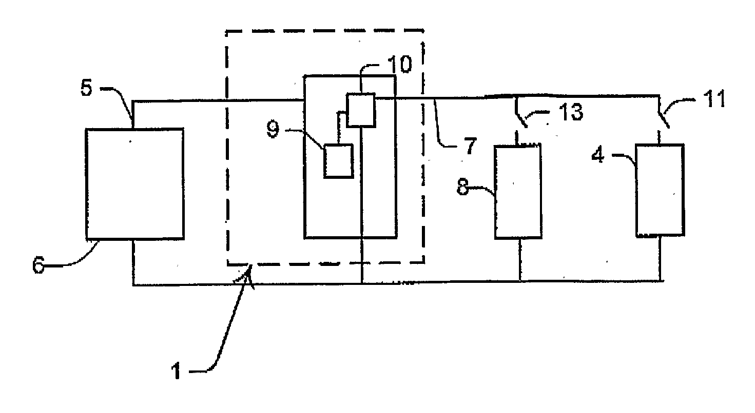
[0053]Preferably also, at least one of the loads is connected to the output by a switch that progresses between an open and a closed configuration for isolating and connecting that load respectively from and with the output. That is, when the switch is in the open configuration and the load is isolated from the output—in that that load is not enabled—the load current for that load will be zero. Conversely, when the switch is in the closed configuration and the respective load is connected with the output—in that that load is enabled—the load current for that load will be non-zero. In a preferred embodiment, the switch is responsive to the
control circuit for progressing between the open and closed configurations. This enables the
voltage presented to the loads to be varied. If the
voltage required to drive one load is too high for any of the other loads, those any other loads are disconnected to reduce the risk of damage to them. Preferably, the switch is a
transistor, and more preferably a FET.
[0054]In some embodiments, the supercapacitive device is always electrically connected to the output. In other embodiments, however, the supercapacitive device is selectively electrically disconnected from the output. More preferably, the supercapacitive device is selectively electrically disconnected from the output in response to the sum of the load currents being below a predetermined threshold for a predetermined period. This saves the supercapacitor leakage current and any supercapacitor balancing circuit current used in conjunction with multi-
cell supercapacitors from draining energy from the power source. Accordingly, for electronic devices having a power source including a secondary battery, the runtime of the device is increased.
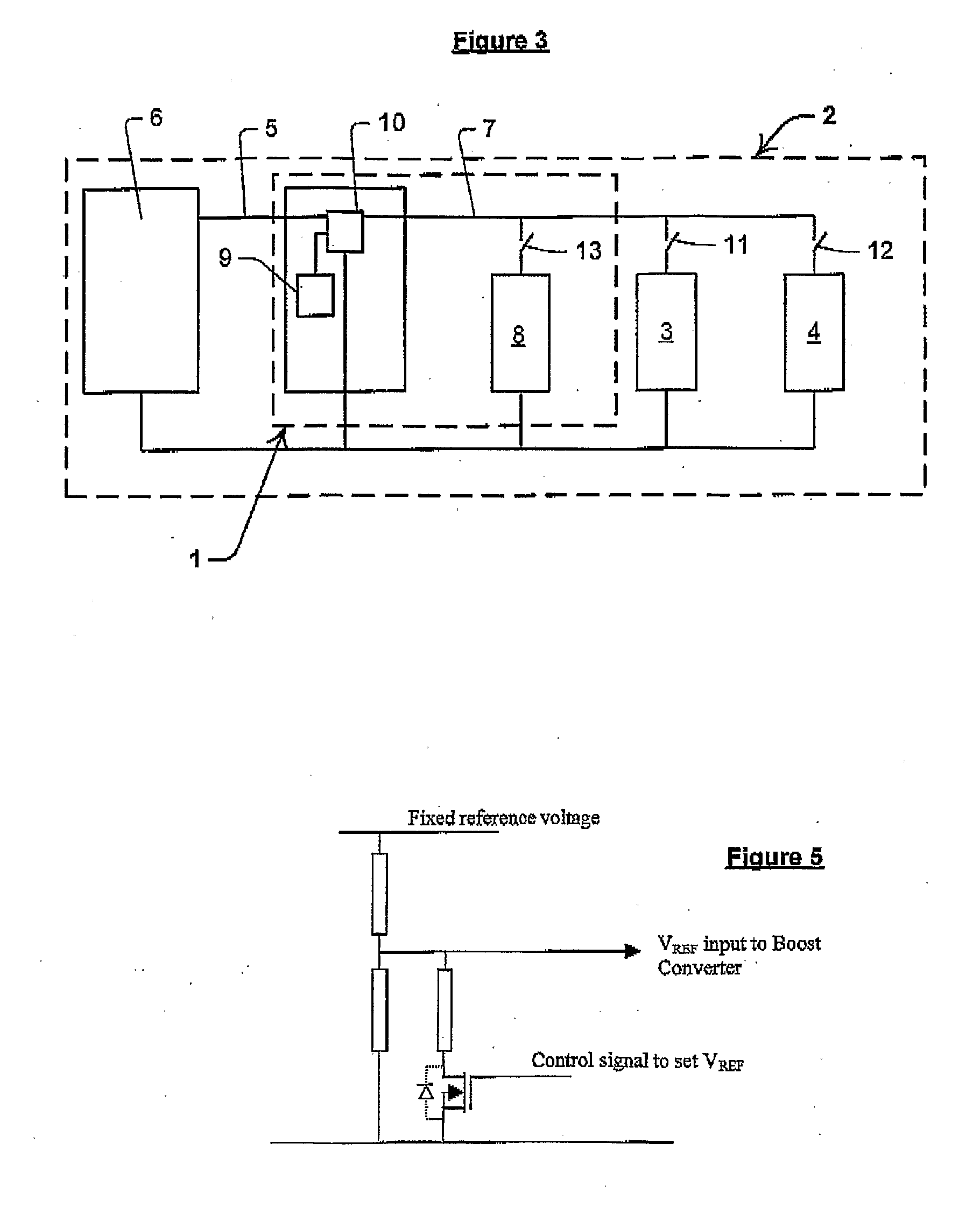
[0056]In a preferred form, at least one of V1, V2, . . . VN is greater than the predetermined source
voltage. More preferably, the
control circuit includes a
regulator that is operable to selectively maintain the output voltage at or about the at least one of V1, V2, . . . VN that is greater than the source voltage. Even more preferably, the regulator is selectively disabled and bypassed with a switch if the source voltage is greater than the selected one Of V1, V2, . . . VN. In preferred embodiments the switch is a FET, while in other embodiments alternative transistors are used. In some embodiments the regulator is a boost circuit, while in other embodiments the regulator is a buck-boost circuit. If a buck-boost circuit is used, there is no need to bypass the regulator with a switch if the source voltage is greater than the required load voltage. This eliminates the switch and its associated
control logic.
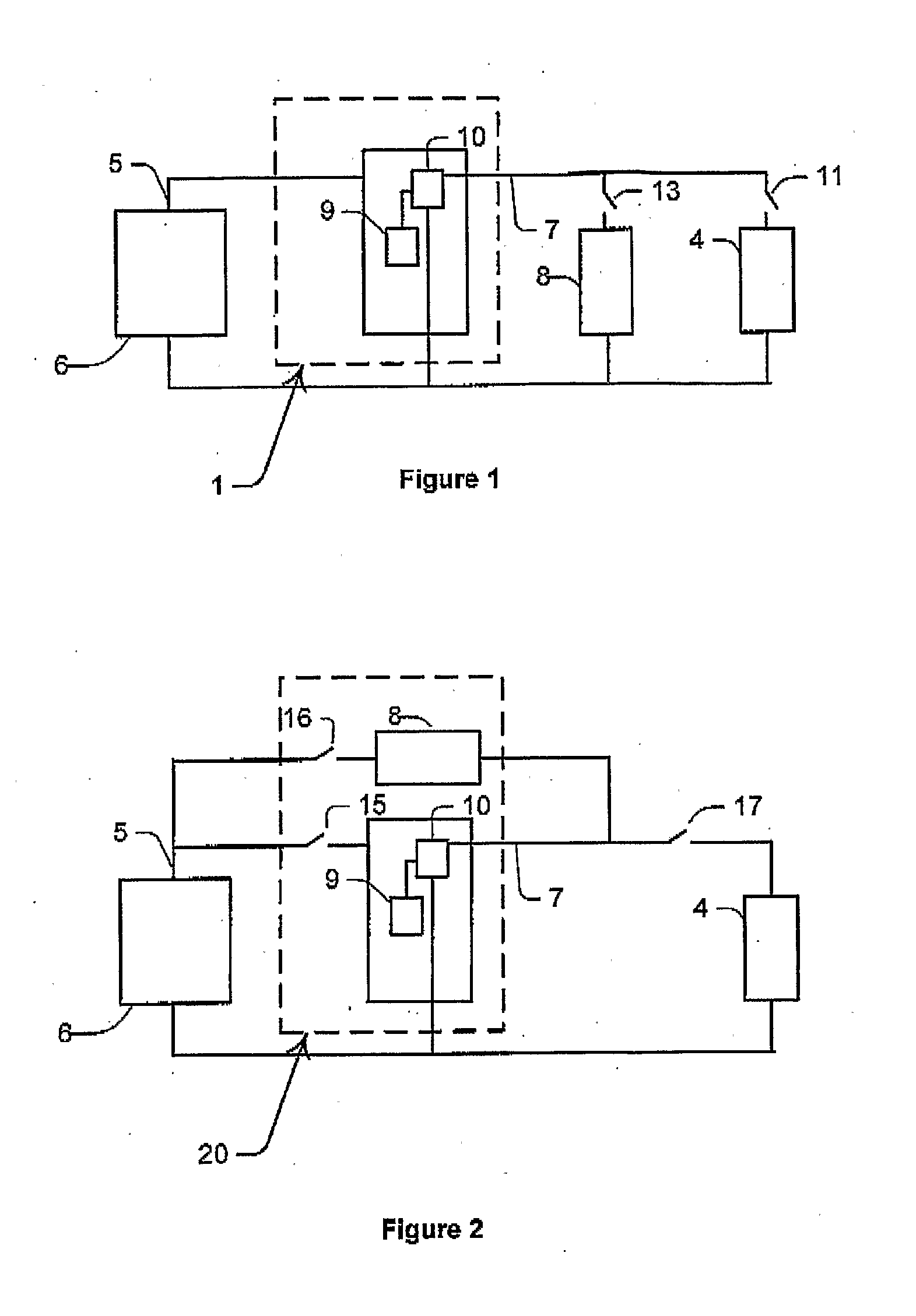
[0078]Preferably also, the
control circuit includes a regulator that is selectively operable for maintaining the output voltage at a predetermined value. More preferably, the operation of the regulator is selected to coincide with the second state. In some embodiments, when the control circuit is in the second state, the output voltage is greater than the source voltage. That is, the regulator is a
boost converter. In other embodiments the output voltage is lower or higher than the source voltage. That is, the regulator is a buck-boost regulator. In further embodiments the output voltage is less than the source voltage and the regulator is a higher
voltage regulator. In embodiments where the regulator is a buck-boost regulator, the regulator automatically takes care of the transition from the first to the second state. The regulator remains enabled and there is no need for a bypass switch. This saves on the bypass switch and associated
control logic, although at the cost of a small efficiency loss of having to still use the buck-boost regulator during the first state.
[0090]Preferably, the control circuit limits the output current to a predetermined maximum even when the output voltage is less than the source voltage. More preferably, the control circuit includes: a regulator in the form of a
boost converter having an
inductor, a FET or other
transistor in series with the
boost converter; and a
diode in series with the
transistor. This prevents high currents flowing to the supercapacitive device until the output voltage is high enough That is, forward conduction of current cannot take place from the source through the
inductor and
diode of the boost converter and to the supercapacitor. This prevents excessive
inrush current when charging the supercapacitor, and maintains the source current below the pre-determined maximum.

