Superconducting single flux quantum modulator circuit

Inactive Publication Date: 2008-06-05
HITACHI LTD
View PDF5 Cites 17 Cited by
  • Summary
  • Abstract
  • Description
  • Claims
  • Application Information

AI Technical Summary

Benefits of technology

[0035]In addition, the analog signal which is inputted into the input inductor can also be inputted into an input inductor of another similar single flux quantum modulator circuit. Therefore, by connecting input inductors of a plurality of simple flux quantum modulator circuits to one another, it is possible to concurrently input one analog signal into the plurality of simple flux quantum modulator circuits. By adding up outputs of the plurality of simple flux quantum modulator circuits, it is possible to reduce the influence of thermal noise and quantization noise exerted upon the decrease i

Problems solved by technology

The thermal noise and leak are causes that decrease

Method used


Image

  • Superconducting single flux quantum modulator circuit
  • Superconducting single flux quantum modulator circuit
  • Superconducting single flux quantum modulator circuit

Examples


Example

First Embodiment

[0052]FIG. 3 is a diagram illustrating a configuration of a single flux quantum modulator circuit 300, which underlies the present invention. The single flux quantum modulator circuit 300 includes: an integration circuit 303 that is formed of an integration inductor 302 and a Josephson junction 301; a comparator 306 that is formed of a pair of junctions constituted of Josephson junctions 304, 305, the comparator 306 being connected to the integration circuit 303; and an input inductor 308 for inputting an analog signal 310. The integrating inductor 302 and the input inductor 308 are magnetically coupled to each other. Because this circuit does not integrate the analog signal 310, this circuit executes delta modulation.

[0053]A first characteristic of the circuit shown in FIG. 3 is that no integration leak occurs. This is because the integration circuit formed of the integrating inductor 302 and the Josephson junction 301 does not include a resistor. A second character...

Example

Second Embodiment

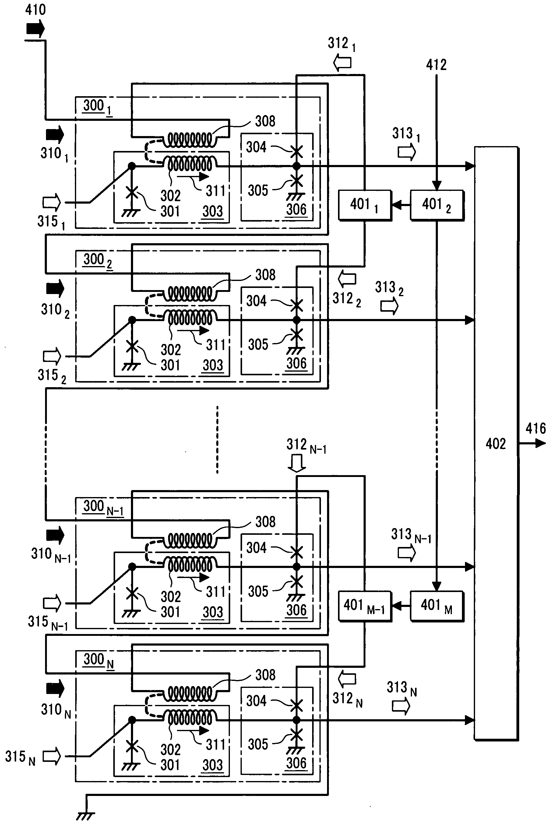
[0058]FIG. 4 is a diagram illustrating as an example a configuration in which a plurality of single flux quantum modulator circuits 300, one of which is shown in FIG. 3 in the first embodiment, are connected to one another so as to increase the bit accuracy. A circuit shown in FIG. 4 includes circuits 3001, 3002, . . . , 300N-1, 300N, each of which is a unit circuit that is equivalent to the simple flux quantum modulator circuit 300 shown in FIG. 3. The circuit shown in FIG. 4 is formed by connecting in series the input inductor 308 of each simple flux quantum modulator circuit 300 to one another. First of all, a SFQ clock signal 412 is split by a splitter circuit 4012. One of the split SFQ clock signals is split by a splitter circuit 4011 to output split signals, which are then supplied to the single flux quantum modulator circuits 3001, 3002 as SFQ clock signals 3121, 3122 respectively. The other split SFQ clock signal which has been split by the splitter circuit ...

Example

Third Embodiment

[0063]FIG. 5 is a diagram illustrating a configuration in which the single flux quantum modulator circuit shown in FIG. 3 according to the first embodiment of the present invention is developed to a sigma-delta modulator. A circuit shown in FIG. 5 is formed by connecting an analog-signal integration resistor 501 to both ends of the input inductor of the single flux quantum modulator circuit 300 according to the first embodiment. How the circuit operates will be described as below.

[0064]An analog signal 310 is integrated by an analog-signal integration circuit that is formed of the input inductor 308 and the analog-signal integration resistor 501. The result of the integration is reflected on a circular current 510 that flows through the input inductor. This circular current is induced into the integrating inductor 302 of the integration circuit 303, the integrating inductor 302 being magnetically coupled to the input inductor 308. The induced circular current is then...


PUM


Abstract

Objects of the present invention are to provide an integration circuit which produces no integration leak so that the bit accuracy is improved in a sigma-delta modulation circuit or a delta modulator circuit, which is based on a single flux quantum circuit that uses a flux quantum as an information carrier, and to provide a method for reducing thermal noise and quantization noise. According to the present invention, an integration circuit is formed by Josephson junctions and an inductor to reduce the integration leak, and a plurality of modulator circuits are connected to one another so as to add up each output. As a result, it is possible to reduce the influence of thermal noise exerted upon the bit accuracy, the thermal noise having no correlativity to one another. Moreover, by changing the density or phase of a SFQ pulse to be supplied to the Josephson junctions of the integration circuit, the correlativity of quantization noise between the outputs of the modulator circuits is eliminated so that the bit accuracy is improved.

Description

CLAIM OF PRIORITY[0001]The present application claims priority from Japanese application JP2006-160615 filed on Jun. 9, 2006, the content of which is hereby incorporated by reference into this application.BACKGROUND OF THE INVENTION[0002]1. Field of the Invention[0003]The present invention relates to a single flux quantum circuit, and more particularly to a method for implementing sigma-delta modulation, or delta modulation, for converting an analog signal into a digital signal.[0004]2. Description of the Related Art[0005]SFQ (Single Flux Quantum) circuits handle a single flux quantum (F0=h / 2e=2.07×10⁻¹⁵ Weber) as an information carrier. These single flux quantum circuits are superconducting circuits that are characterized by ultrahigh-speed operation whose speed is the order of several tens of gigahertz (109 Hz) or higher, and low-power property whose level is several microwatts (μW) per gate or lower. On the basis of the principles shown in IEEE Transaction on Applied Superconduct...

Claims


Application Information

Patent Timeline
IPC IPC(8): H03K17/92
CPCH03K17/14H03K17/16H03K17/92H03M3/456H03M3/418H03M3/43H03M3/02
Inventor FURUTA, FUTOSHISAITOH, KAZUO
Owner HITACHI LTD
Why Eureka
Try Eureka