Vehicle heat exchanger

Active Publication Date: 2015-10-29
DENSO CORP
View PDF4 Cites 5 Cited by
  • Summary
  • Abstract
  • Description
  • Claims
  • Application Information

AI Technical Summary

Benefits of technology

[0011]According to the disclosure described above, the low-temperature side radiator forms the coolant flow channel which is constituted of the inflow portion, the upper path, the lower path, and the outlet portion and extends from the upper side to the lower side. Furthermore, the subcooler of the condenser overlaps, in the airflow direction, with at least a part of the lower path of the low-temperature side radiator.

Problems solved by technology

Accordingly, there is a concern that heat generated by the low-temperature side radiator may be tra

Method used


Image

  • Vehicle heat exchanger
  • Vehicle heat exchanger
  • Vehicle heat exchanger

Examples


first embodiment

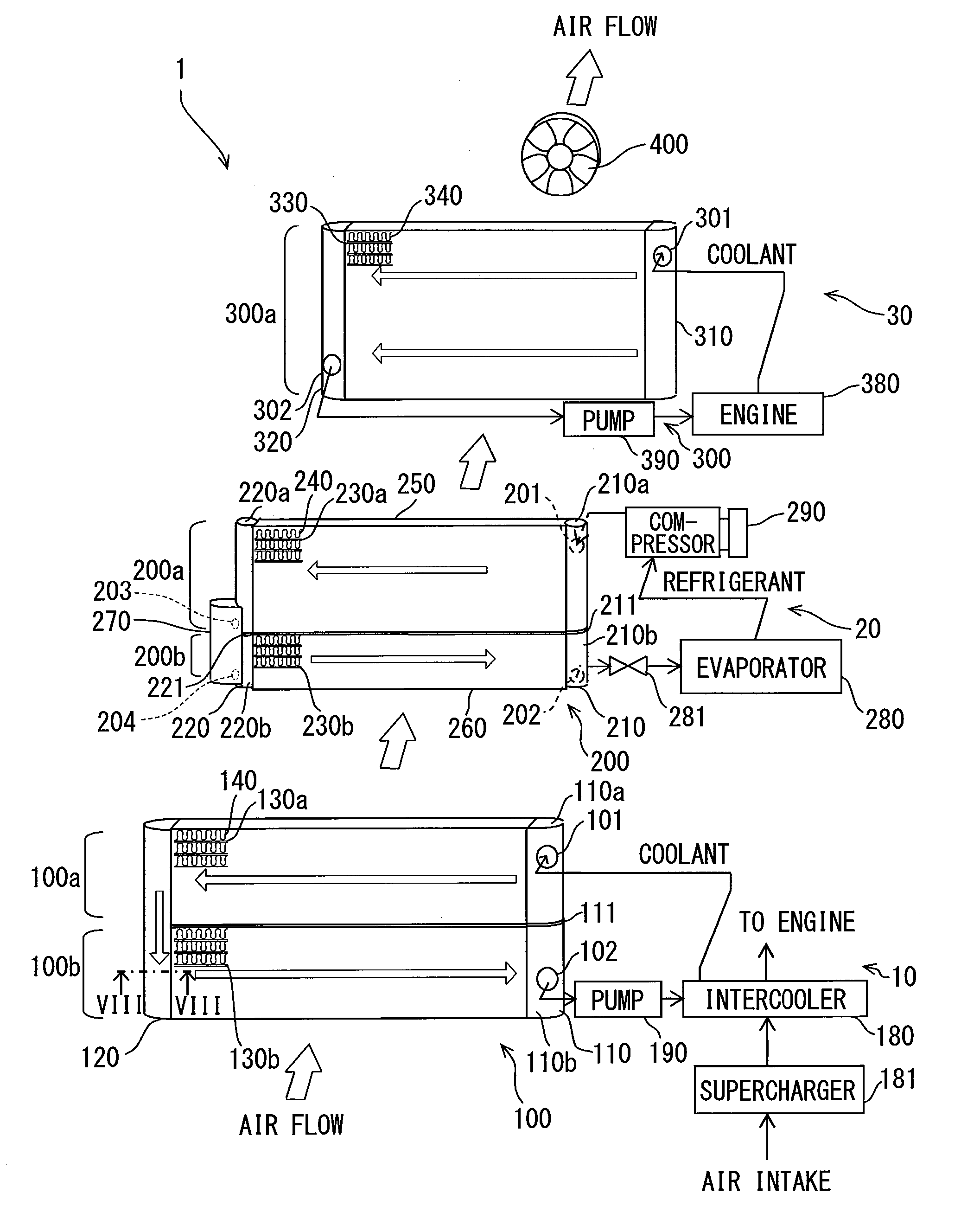
[0026]A first embodiment according to the present disclosure will be described. A vehicle heat exchanger 1 illustrated in FIG. 1 constitutes an Engine Cooling Module (ECM) and includes a low-temperature side radiator 100, a condenser 200, a high-temperature side radiator 300, and a fan 400. The vehicle heat exchanger 1 is mounted on a vehicle which includes an internal combustion engine (an engine 380), a supercharger 181 included in the engine 380, an intercooler 180 for cooling intake air which is compressed by the supercharger 181, and a refrigeration cycle 20 constituting a car air conditioner.

[0027]Next, the details of a low-temperature side coolant cycle 10, in which the intercooler 180, the low-temperature side radiator 100, and a low-temperature side pump 190 are connected to one another through piping to form a circuit, are described with reference to FIG. 1. The intercooler 180 performs heat exchange between intake air supercharged by the supercharger 181 and coolant to co...

modification example of first embodiment

[0077]FIG. 9 illustrates a cross-sectional surface of a second tank 120k according to a modification example of the first embodiment. The second tank 120k includes a tank body portion 125k and a tank base portion 122k. The tank body portion 125k is a half-rectangular-tube-shaped member formed of, for example, an aluminum alloy. The tank base portion 122k is a semicylinder-shaped member formed of, for example, an aluminum alloy. The tank base portion 122k is joined to the tank body portion 125k by, for example, soldering or brazing. The second tank 120k according to the modification example can have a robust structure having high heat-resisting properties, compared to the second tank 120 according to the first embodiment, which is formed of a resin.

second embodiment

[0078]Next, a second embodiment will be described. The same reference numerals and letters are given to members of which the configurations are the same as those of the first embodiment described above. The detailed descriptions thereof will be omitted for brevity.

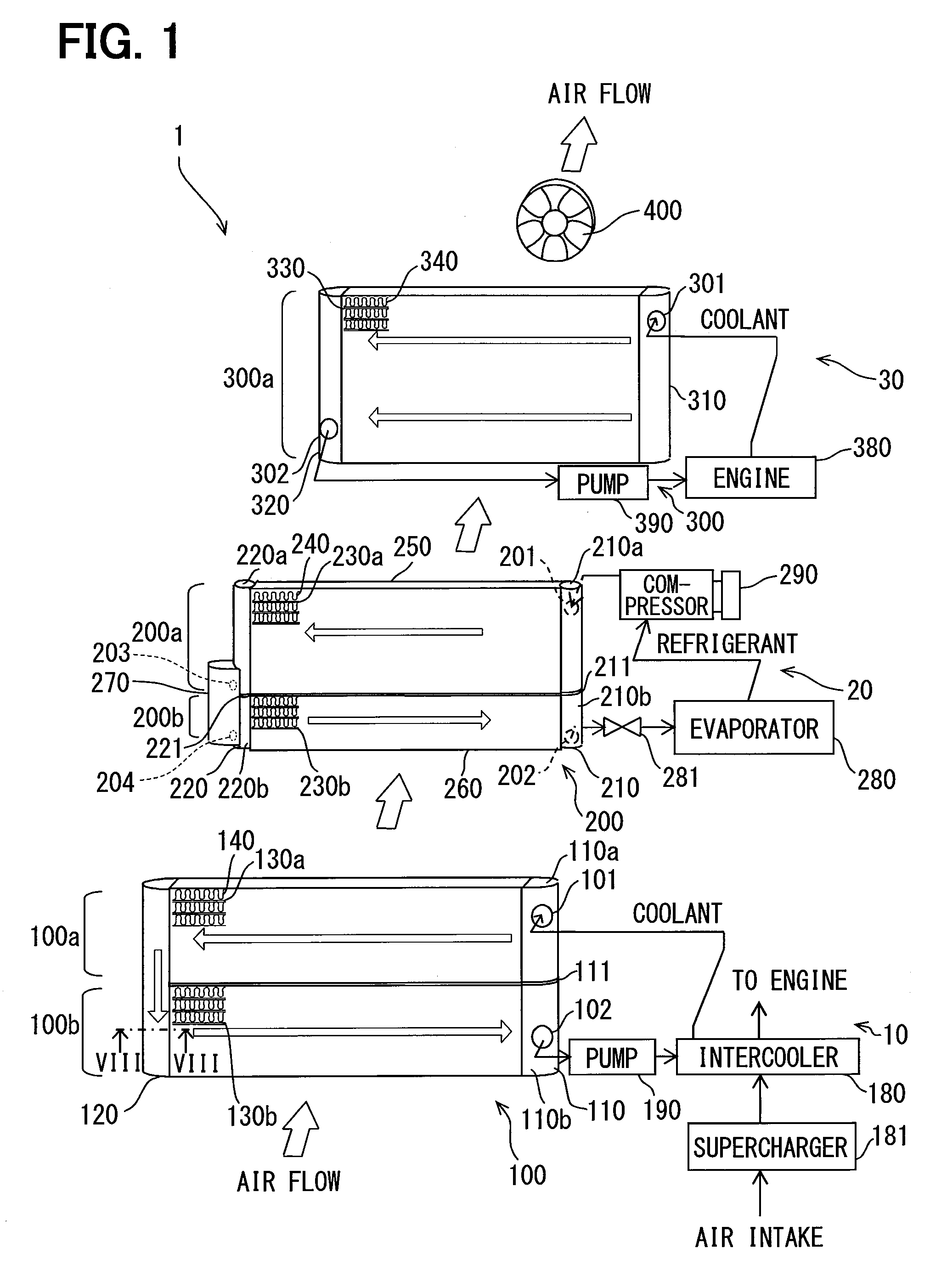
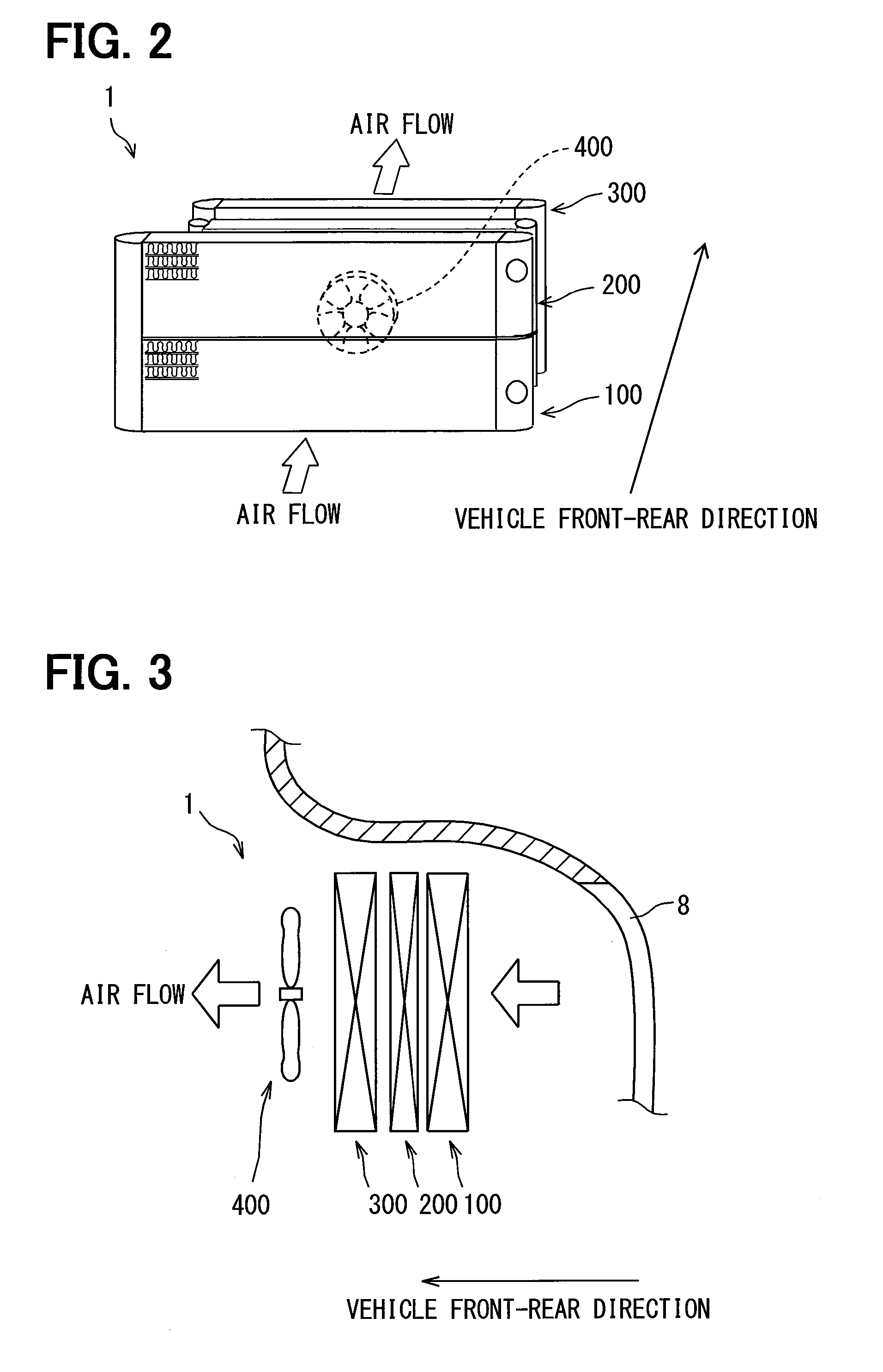
[0079]In a vehicle heat exchanger 1a illustrated in FIG. 10, the condenser 200, the low-temperature side radiator 100, and the high-temperature side radiator 300 are aligned in this order in the airflow direction. In such a configuration, the condenser 200 is located in the frontmost row of the vehicle heat exchanger 1 in the front-rear direction of the vehicle. Thus, the condenser 200 can be allowed to have a large heat exchange area with respect to the air. Accordingly, fresh air entering the vehicle 8 can be preferentially supplied to the condenser 200, and thus the refrigerant of the condenser 200 can be cooled by being effectively subjected to heat exchange.

[0080]After being condensed by the compressor 290, the high-p...


PUM


Abstract

A vehicle heat exchanger includes a low-temperature side radiator, a condenser, and a high-temperature side radiator, which are aligned in an airflow direction and are integrated together. The low-temperature side radiator includes an inflow portion and an upper path, which are located in an upper portion thereof. In addition, the low-temperature side radiator includes a lower path and an outlet portion, which are located in a lower portion thereof and communicate with the upper path. A subcooler of the condenser overlaps, in the airflow direction, with at least a part of the lower path of the low-temperature side radiator. As a result, thermal influence by the low-temperature side radiator on the subcooler of the condenser can be reduced.

Description

CROSS-REFERENCE TO RELATED APPLICATION[0001]The present application is based on Japanese Patent Application Nos. 2012-270640 and 2013-249399 filed on Dec. 11, 2012 and Dec. 2, 2013, respectively, the content of which is incorporated herein by reference.TECHNICAL FIELD[0002]The present disclosure relates to a vehicle heat exchanger.BACKGROUND ART[0003]A vehicle heat exchanger which includes, in addition to a high-temperature side radiator used for cooling an internal combustion engine (an engine), a low-temperature side radiator used for cooling an inverter for controlling a drive motor or cooling a supercharger, such as a turbocharger, is known conventionally. A vehicle heat exchanger disclosed in, for example, Patent Literature 1 includes, in addition to the high-temperature side radiator described above, a low-temperature side radiator used for cooling an inverter for controlling a drive motor. In the configuration disclosed in Patent Literature 1, in addition to the high-temperat...

Claims


Application Information

Patent Timeline
IPC IPC(8): B60H1/00
CPCB60H1/00328B60K11/04F28F9/0224F28D1/0452F28D1/05391F28F2210/08F01P2003/182B60H1/00335
Inventor OONO, SHINGOAKAGI, SHOTA
Owner DENSO CORP
Why Eureka
Try Eureka