Exposure apparatus and device manufacturing method

Inactive Publication Date: 2010-03-04
CANON KK
View PDF9 Cites 9 Cited by
  • Summary
  • Abstract
  • Description
  • Claims
  • Application Information

AI Technical Summary

Benefits of technology

[0013]The present invention is provided to reduce a thermal influence exerted by a vacuum pump on a st

Problems solved by technology

For example, if the radiation unit is provided around the cryo panel, around the opening of a duct of the

Method used


Image

  • Exposure apparatus and device manufacturing method
  • Exposure apparatus and device manufacturing method
  • Exposure apparatus and device manufacturing method

Examples


Example

First Embodiment

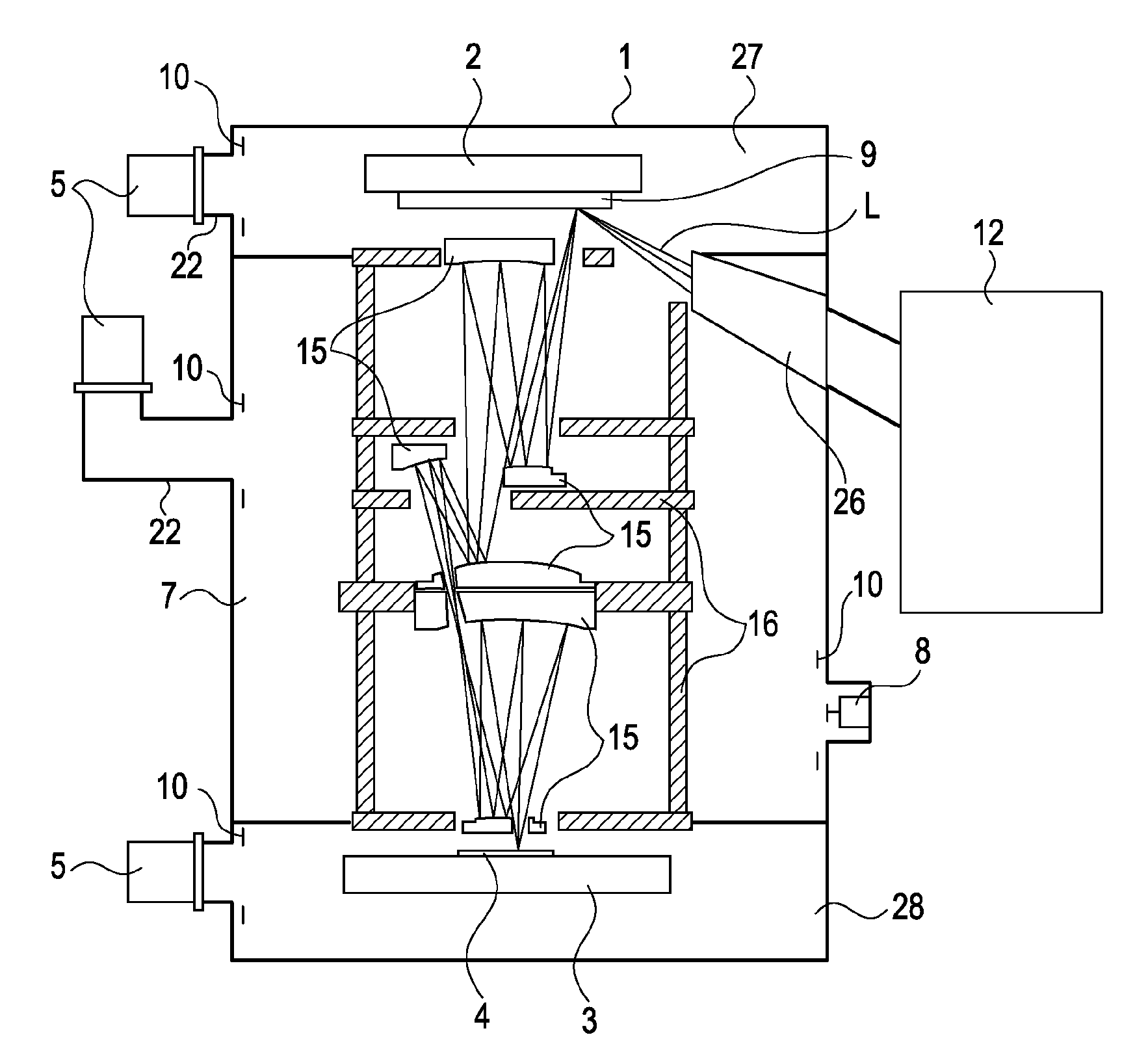
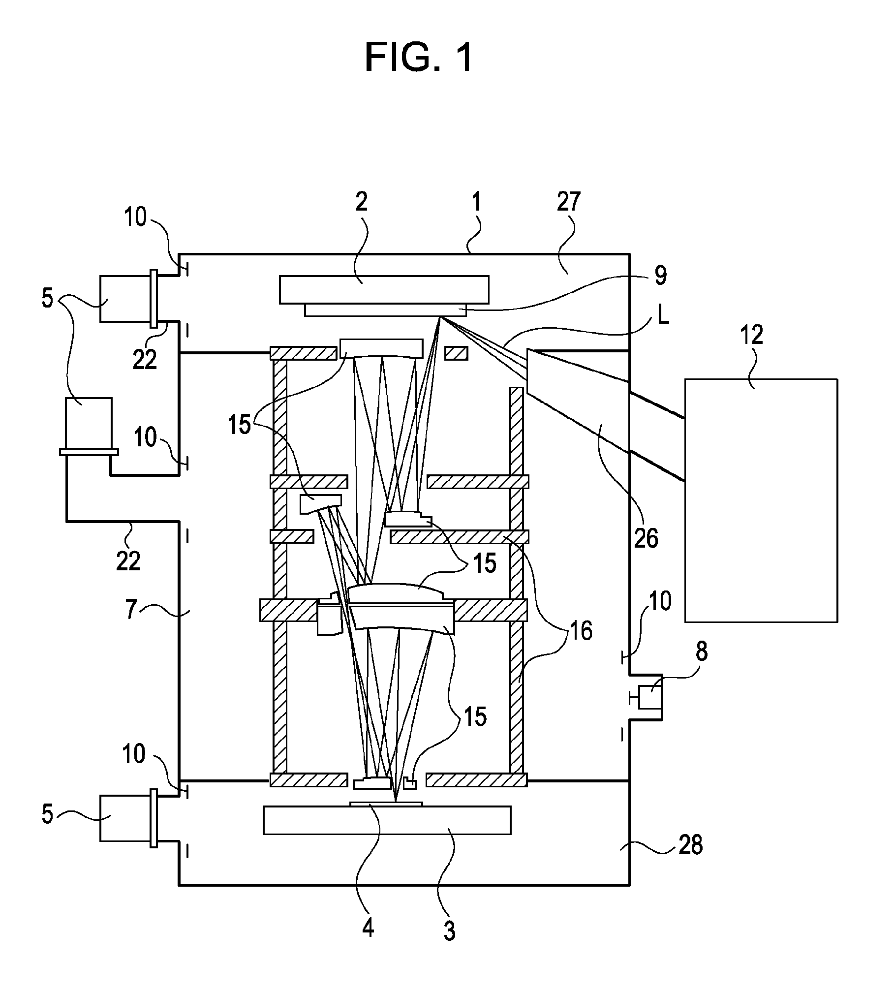
[0028]FIG. 1 is a schematic configuration diagram of an exposure apparatus according to a first embodiment of the present invention. The above-described exposure apparatus includes a light source 12 emitting EUV light. The interior of the exposure apparatus is hermetically sealed in a vacuum chamber (vacuum container) 1, and the interior of the vacuum chamber 1 is evacuated to vacuum through a turbo molecular pump (vacuum pump) 5. EUV light L emitted from the light source 12 is reflected from a reticle 9 held on a reticle stage 2 and optical elements 15 that are included in a projection optical system so that a wafer 4 placed on a waver stage 3 is irradiated with the EUV light L. Consequently, the circuit pattern of the reticle 9 is projected onto the wafer 4.

[0029]The vacuum chamber 1 is separated into illumination-optical-system space 26, reticle-stage space 27, wafer-stage space 28, and projection-optical-system space 7. Each of the above-described spaces is provi...

Example

[0048]FIG. 5 is a diagram schematically showing the principal mechanism of a second embodiment of the present invention. The descriptions of the same configurations as those of the first embodiment will be omitted.

[0049]The above-described embodiment is different from the first embodiment in that a cryo pump 8 is used as the vacuum pump. The cryo pump 8 is provided so that a carbon compound generated by irradiating a resist applied on the wafer 4 with EUV light is absorbed in a cooling face 25 which is kept at a temperature of 70K or around, and the density of the carbon compound of the projection-optical-system space 7 is decreased.

[0050]Since the cryo pump 8 uses the cooling face 25 kept at a temperature of 70K or around, a thermal influence exerted on the barrel 16 or the like should be reduced.

[0051]Therefore, according to the above-described embodiment, the radiation member 10 is provided around the cooling face 25 of the cryo pump 8. The radiation member 10 is arranged at a po...

Example

Third Embodiment

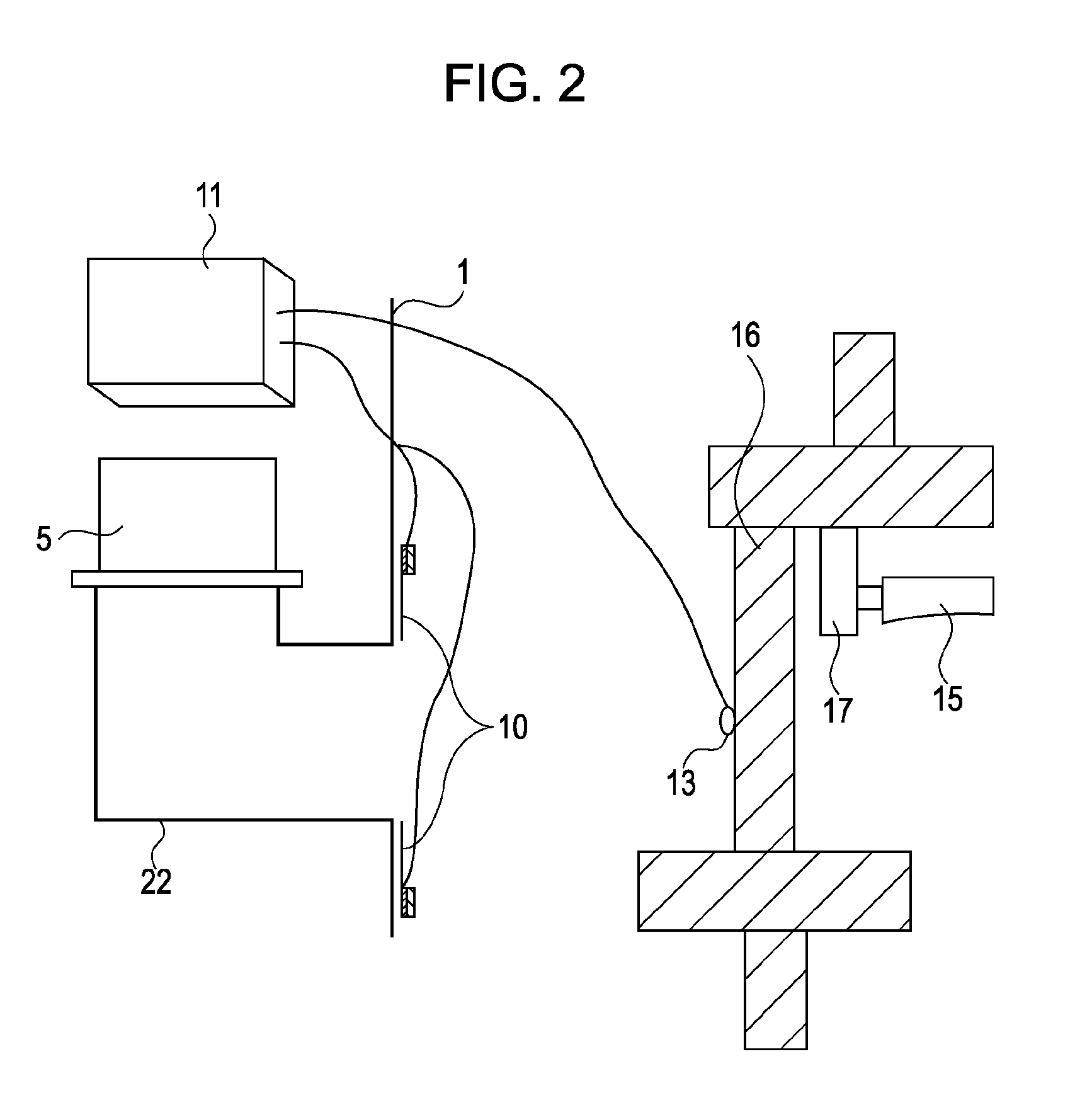
[0061]FIG. 6 is a diagram schematically showing the principal mechanism of a third embodiment of the present invention. The descriptions of the same configurations as those of the first embodiment will be omitted.

[0062]The above-described embodiment is different from the first embodiment in that the temperature sensor 13 is attached to a reference temperature member 14.

[0063]The reference temperature member 14 of the above-described embodiment is provided between the opening of the duct 22 connecting the turbo molecular pump 5 to the vacuum chamber 1 and the barrel 16, and on the central axis of the duct 22. However, since the reference temperature member 14 is sufficiently small for the opening of the duct 22, the reference temperature member 14 hardly reduces the evacuation efficiency of the turbo molecular pump 5.

[0064]The reference temperature member 14 includes a material having a high radiation rate, or is processed to increase the radiation rate of the top fac...


PUM


Abstract

An exposure apparatus of the present invention includes a vacuum container accommodating a structure, a vacuum pump configured to increase the degree of vacuum achieved inside the vacuum container, a radiation unit configured to perform a heat exchange through radiation for the structure, a temperature detecting unit configured to detect the temperature of the structure, and a control unit configured to control the radiation unit based on the detected temperature, wherein the radiation unit is arranged at a position determined so that the radiation unit does not interfere with a heat exchange achieved through radiation between the vacuum pump and the structure.

Description

BACKGROUND OF THE INVENTION[0001]1. Field of the Invention[0002]The present invention relates to an exposure apparatus exposing a substrate to light and particularly relates to an exposure apparatus including a vacuum pump which evacuates the interior of the exposure apparatus.[0003]2. Description of the Related Art[0004]Exposure apparatuses that project a circuit pattern written on a reticle (mask) on a wafer or the like through a projection optical system have been used to manufacture a minute semiconductor element including a memory, a logic circuit, and so forth.[0005]The minimum critical dimension (resolution) that can be transferred through the exposure apparatus is proportional to the wavelength of light used to perform an exposure and is inversely proportional to the numerical aperture (NA) of the projection optical system. Therefore, the wavelength of light used to perform an exposure has become increasingly shorter in accordance with the need for micro-miniaturizing the se...

Claims


Application Information

Patent Timeline
IPC IPC(8): G03F7/20G03B27/52
CPCG03B27/52G03F7/70891G03F7/70841
Inventor NAMBA, HISASHI
Owner CANON KK
Why Eureka
Try Eureka