Forward throw antenna utility meter

a technology of forward throw and utility meters, applied in the field of electric meters, can solve the problems of not conveying communication systems, measuring not characterizing over the air, radio frequency performance of communication systems, etc., and determining how small a signal the communication systems could “hear

Inactive Publication Date: 2008-06-05
ITRON +1
View PDF7 Cites 252 Cited by
  • Summary
  • Abstract
  • Description
  • Claims
  • Application Information

AI Technical Summary

Benefits of technology

[0011]The present invention provides systems and methods for a forward throw antenna utility meter for use in wireless meter reading applications. One embodiment provides a utility meter assembly comprising: a plurality of meter components configured for measuring and collecting data, the meter components including a transceiver operative for signal communications over a wireless network; a faceplate, configured such that meter reading information is displayed on the front of the faceplate; an exterior cover configured to enclose mete

Problems solved by technology

However, these measurements did not characterize the over the air, radio frequency performance of communication systems.
They did not convey the communication systems' sensitivity (its ability to receive low signals), that is, they did not determine how small a signal the communication systems could “hear” or receive.
Further, the certification measurements did not characterize the total radiated power from the communication systems during transmission.
Consequently, communication systems experienced connectivity and retransmission problems because of inadequately characterized radio frequency product performance.
Unreliable connectivity, dropped calls, and data retransmission problems adversely affected the quality of service.
Communication systems which do not conform to these new performance requirements are not certified or granted access to the wireless carrier's network.
Wireless electricity meters that used previous antenna designs failed to pass these new and stringent certification r

Method used


Image

  • Forward throw antenna utility meter
  • Forward throw antenna utility meter
  • Forward throw antenna utility meter

Examples


Embodiment Construction

[0041]Reference is now made in detail to the description of the embodiments of systems and methods for automatic configuration of a generic digital device on a wireless network as illustrated in the drawings. The invention may, however, be embodied in many different forms and should not be construed as limited to the embodiments set forth herein; rather, these embodiments are intended to convey the scope of the invention to those skilled in the art. Furthermore, all “examples” given herein are intended to be non-limiting.

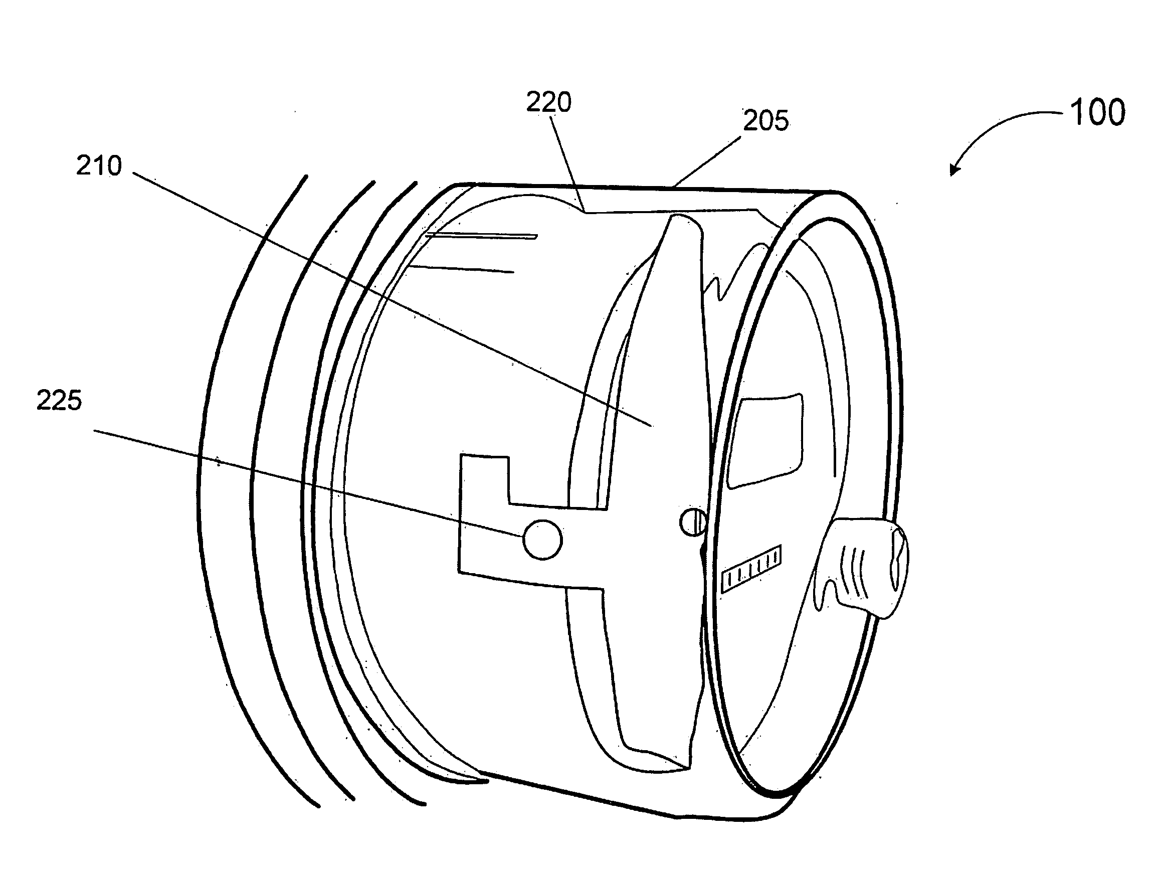
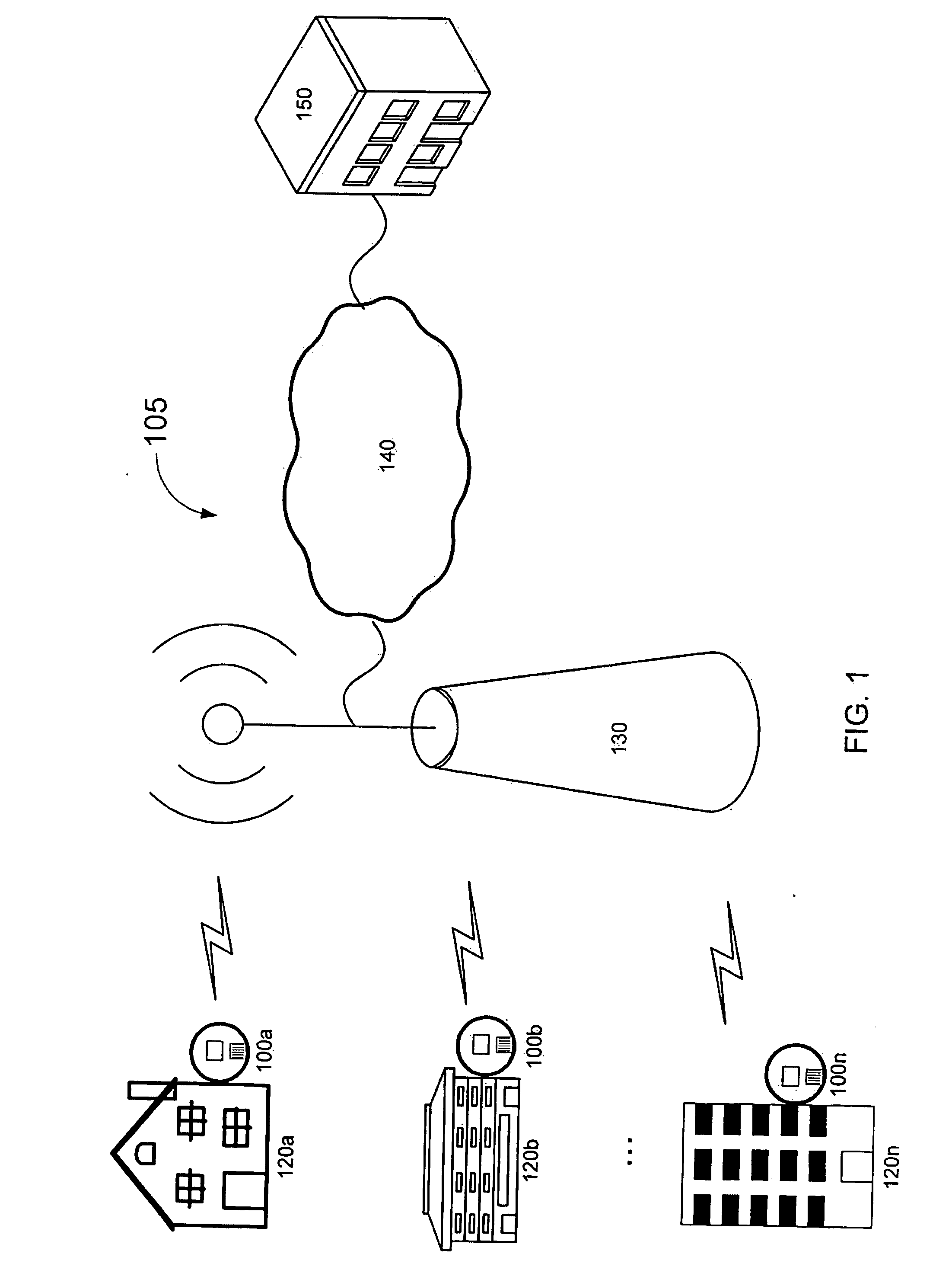
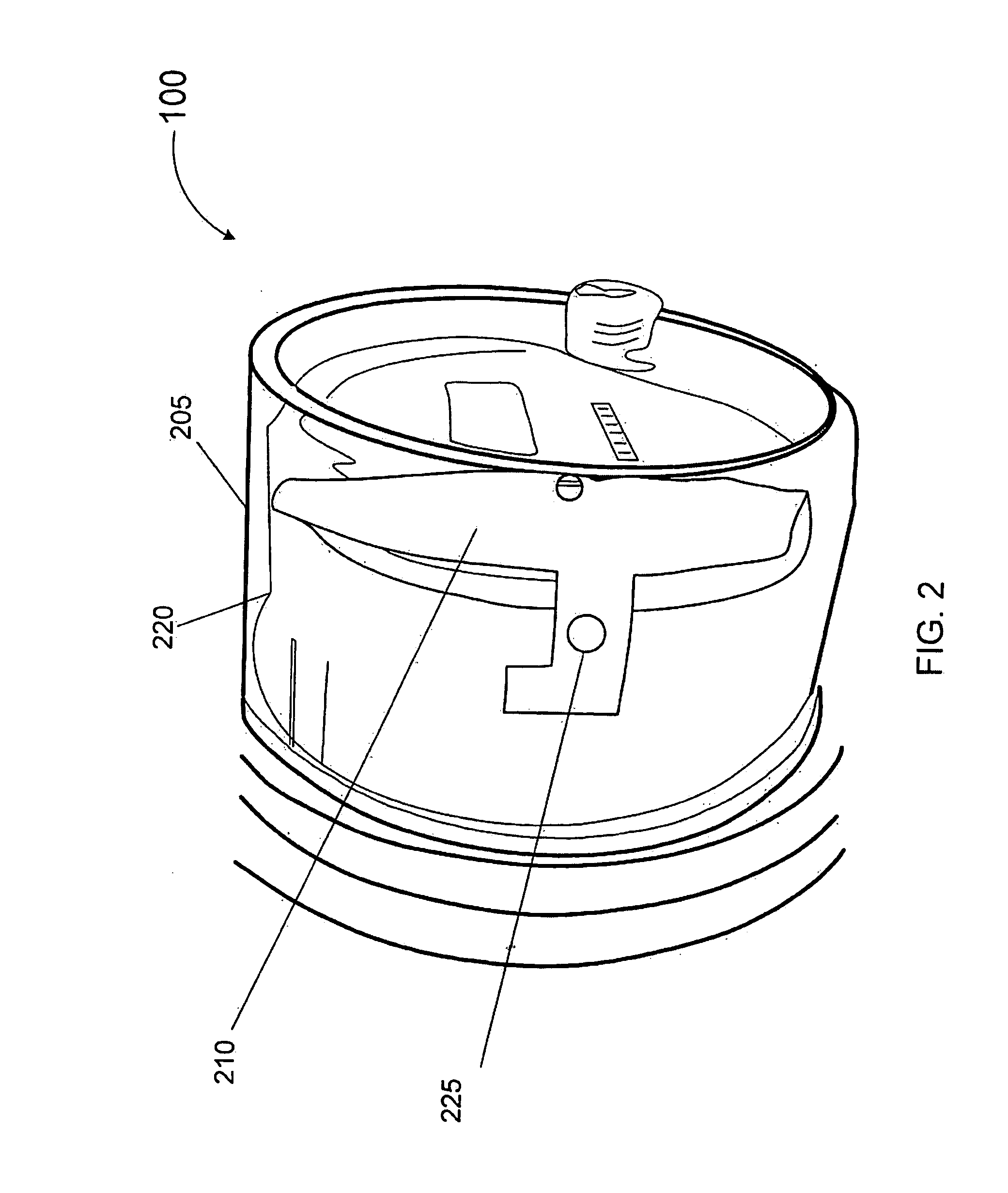
[0042]Turning attention to the drawings, FIG. 1 illustrates an exemplary embodiment of a remote meter reading system 105 for reading utility meters using a wireless network. The remote meter reading system 105 comprises wireless utility meters 100a, 100b, 100n located at respective client sites 120a, 120b, 120n. Of course the remote meter reading system 105 may contain any number of client sites 120 and wireless utility meters 100. The wireless utility meter 100 com...


PUM

PropertyMeasurementUnit
Lengthaaaaaaaaaa
Lengthaaaaaaaaaa
Thicknessaaaaaaaaaa

Abstract

Systems and methods are provided for a utility meter assembly comprising: a plurality of meter components configured for measuring and collecting data, wherein the meter components include a transceiver operative for signal communications over a network; a faceplate, configured such that meter reading information is displayed on the front of the faceplate; an exterior cover configured to enclose the meter components and the faceplate, wherein the faceplate is forward of the plurality of meter components; and an internal dipole antenna situated within the exterior cover, wherein the internal dipole antenna is beyond the front of the faceplate and toward the front of the utility meter assembly. The internal dipole antenna is typically situated away from the meter components, so as to minimize interference by the meter components. The internal dipole antenna is typically tuned for optimal matching impedance in an 850 MHz or 1900 MHz receiving band, so that the desired receiving band Standing Wave Ration (SWR) is achieved, and also a specified minimum radiated power threshold is maintained.

Description

CROSS-REFERENCE TO RELATED APPLICATIONS[0001]This application claims the benefit under 35 U.S.C. § 119(e) of U.S. Provisional Patent Application Ser. No. 60 / 864,201, entitled “Improved Antenna Used in Electricity Metering Applications,” filed Nov. 3, 2006, which is incorporated herein by reference as if set forth herein in its entirety.TECHNICAL FIELD[0002]The present invention relates generally to electricity meters, and more particularly, to an improved antenna design that provides improved total radiated power and total isotropic sensitivity in a communication system intended for use on a public wireless network.BACKGROUND OF THE INVENTION[0003]In remote meter reading systems, such as wireless metering applications, wireless utility meters are read without visual inspection or physical access to the meters. Wireless utility meters intended for use on wireless networks are required to undergo a certification process before they are granted carrier approval for network access.[0004...

Claims


Application Information

Patent Timeline
IPC IPC(8): H01Q9/16G08B23/00
CPCY10T29/49018H01Q1/2233
Inventor RANDALL, BRUCE E.BUCHANAN, WILLIAM MEDFORDSEAL, ROBERT BRYAN
Owner ITRON
Why Eureka
Try Eureka