
Apparatus at a spinning preparatory plant for detecting foreign objects in fibre material

Inactive Publication Date: 2008-06-05
TRUETZSCHLER GMBH & CO KG
View PDF12 Cites 4 Cited by
  • Summary
  • Abstract
  • Description
  • Claims
  • Application Information

AI Technical Summary

Benefits of technology

[0005]It is an aim of the invention to produce an apparatus of the kind described initially that avoids or mitigates the said disadvantages and which in particular in a simple manner permits the at least one transparent region to be kept clean in operation and allows the foreign objects to be detected without hindrance.
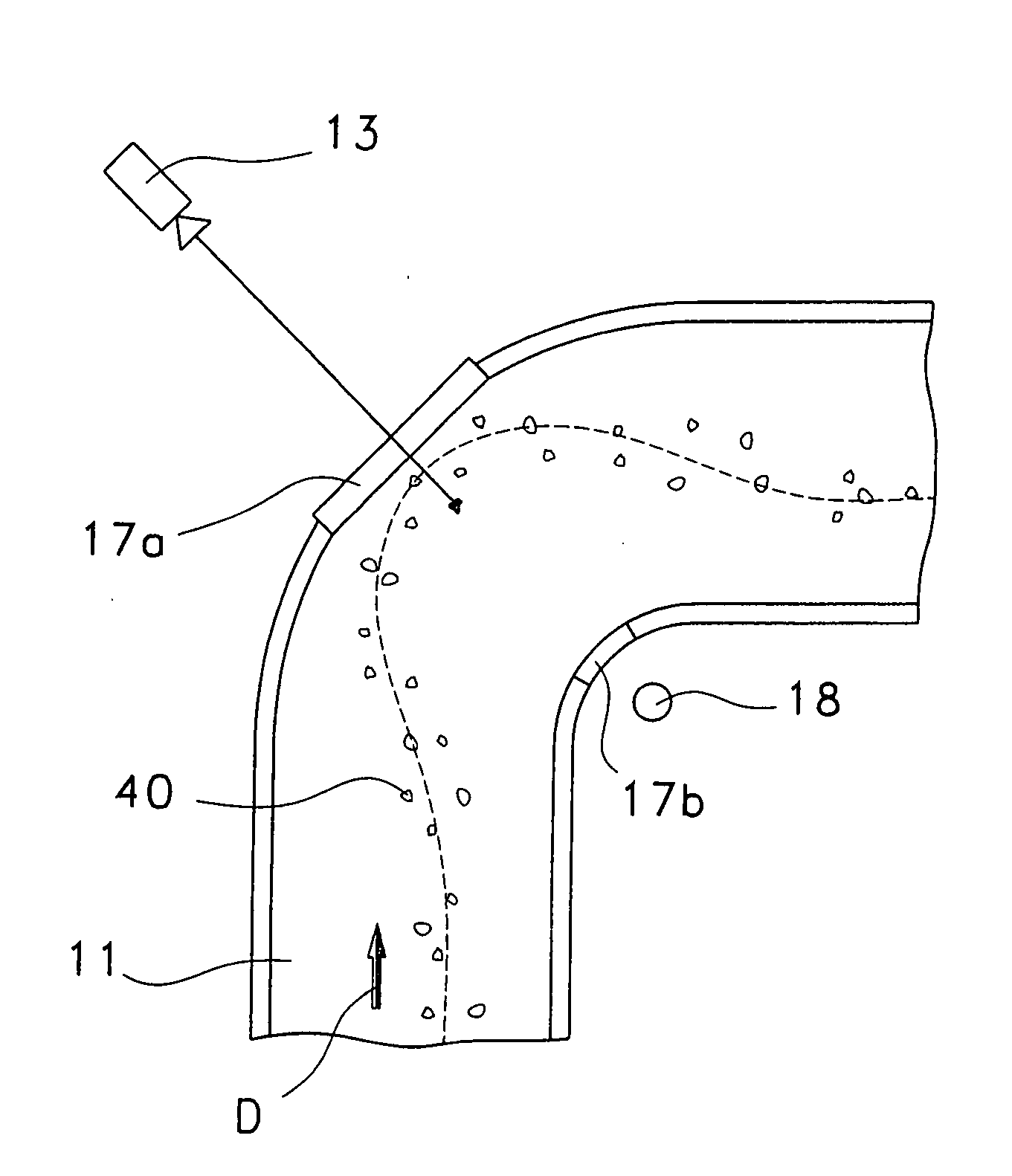
[0007]Because the fibre-air flow flows during operation along the transparent region in force-applying contact therewith, self-cleaning is effected in a simple manner. In this case, the cleaning action of the fibre-air flow is greater than the contaminating action; any impurities deposited are wiped away. The transparent region, for example, a glass pane, is advantageously protected in this way from contamination by substances contained in the fibre material, or by impurities carried along in the fibre-air flow outside the fibre material. The contact force is essentially brought about by the fibre-air flow impacting the transparent region. The contact force is preferably reinforced by the fact that the transparent region constricts the cross-section of the fibre transport duct, with the result that the pressure of the fibre-air flow increases.

Problems solved by technology

One problem in the operation of this optically functioning foreign part detector is that the necessary interface, usually glass or plastics, between the area of the fibre material flow and the area with the optical components becomes contaminated with the substances contained in the fibre material, such as dust, honeydew or finishing agents, or impurities carried along in the fibre-air flow.
This contamination impairs the function of the foreign part detector, thus necessitating service intervals for cleaning that are unacceptable to the operators.
The same problems exist in the application of optical measuring apparatus that looks into fibre-carrying channels of spinning preparatory machines.

Method used


Image

  • Apparatus at a spinning preparatory plant for detecting foreign objects in fibre material
  • Apparatus at a spinning preparatory plant for detecting foreign objects in fibre material
  • Apparatus at a spinning preparatory plant for detecting foreign objects in fibre material

Examples


Embodiment Construction

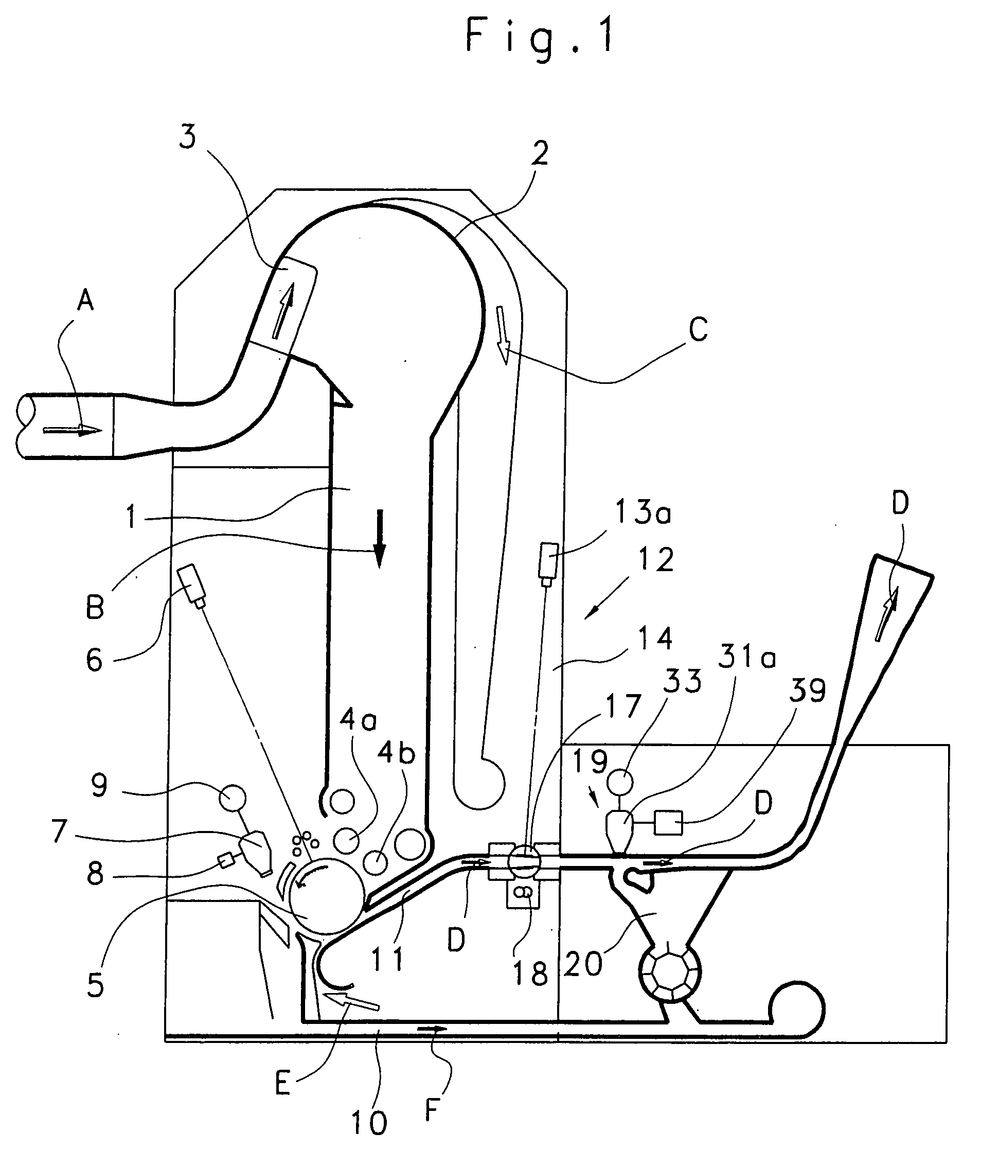
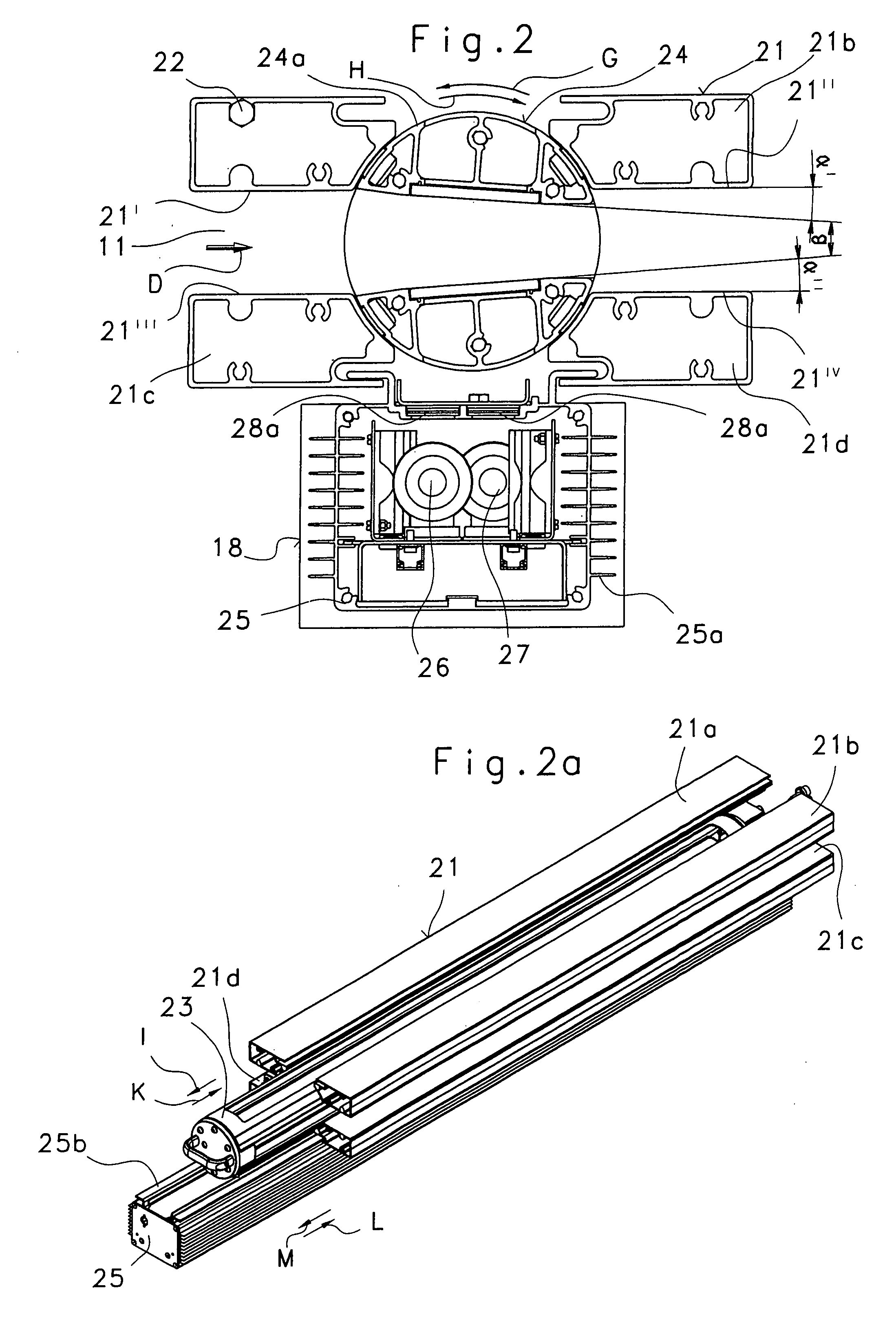
[0022]Referring to FIG. 1, in an apparatus for detecting and separating foreign objects, e.g. the foreign part separator SECUROMAT SP-F2 made by Trützschler GmbH & Co. KG of Mönchengladbach, Germany, the upper inlet opening of a feed chute 1 has associated with it an arrangement for the pneumatic supply of a fibre-air flow A, which comprises a fibre material transport fan (not shown), a stationary air-permeable surface 2 for removal (separation) of the fibre material B from air C with air extraction, and an air flow guide means 3 with movable elements; the fibre material present in the air flow is guided reversibly backwards and forwards transversely over the air-permeable surface 2 and, following impact, the fibre material falls substantially as a result of gravity from the air-permeable surface 2 and enters the feed chute 1 downwards. The slow-speed rollers 4a, 4b have a dual function: they serve as take-off rolls for the fibre material B out of the feed chute 1 and at the same ti...


PUM


Abstract

In an apparatus at a spinning preparatory plant for detecting foreign objects, for example, pieces of cloth, tapes, string, pieces of sheeting and the like, in fibre material, the fibre material is transportable in an air flow through a fibre transport duct or a feed chute and an optical sensor system is associated with the duct or chute, the wall surfaces of which have at least one transparent region through which the sensor system detects the fibre-air flow. To permit the at least one transparent region to be kept clean in a simple manner during operation, and to permit an unobstructed detection of the foreign objects, the transparent region projects into the fibre-air flow and the fibre-air flow is able to flow along the transparent region in force-applying contact therewith.

Description

CROSS REFERENCE TO RELATED APPLICATION[0001]The present application claims priority from German Patent Application No. 10 2006 057 215.7, dated Dec. 1, 2006, the entire disclosure of which is incorporated herein by reference.BACKGROUND OF THE INVENTION[0002]The invention relates to an apparatus at a spinning preparatory plant for detecting foreign objects, for example, pieces of cloth, tapes, string, pieces of sheeting and the like in the fibre material, for example, cotton and / or synthetic fibres.[0003]It is known, in a spinning preparatory installation, in which the fibre material is transportable in a current of air through a fibre transport duct or a feed chute and an optical sensor system is associated with the fibre transport duct or the feed chute, for the wall surfaces of the duct or chute to have at least one transparent region through which the sensor system detects the fibre-air flow.[0004]In the case of a known apparatus (DE 10 2005 014 898 A1), the fibres are transporte...

Claims


Application Information

Patent Timeline
IPC IPC(8): G01N21/89D01G31/00
CPCD01G23/08D01G31/003D01G31/00
Inventor ENGELS, GUIDONOHR, FRANZTEMBURG, KONRAD
Owner TRUETZSCHLER GMBH & CO KG
Learn More