Optical fiber amplifying module

Inactive Publication Date: 2008-06-05
MEGAOPTO
View PDF9 Cites 17 Cited by
  • Summary
  • Abstract
  • Description
  • Claims
  • Application Information

AI Technical Summary

Benefits of technology

[0010]The present invention has been developed to eliminate the problems described above. It is an object of the present invention to provide a

Problems solved by technology

That is, when the ratio at which the amplified spontaneously emitted light (ASE) component mingles increases in an optical fiber amplifying module so that the extinction ratio of output pulse trains deteriorates, the output of the optical fiber amplifying module is saturated with the ASE light, which makes it harder to attain the high gain.
When lasers for processing and the like have a very low duty cycle, e.g., 1 / 100 to 1 / 10000, however, pulse peaks are hard to detect, whereby active control such as the one disclosed in Patent Document 1 may yield a high risk of malfunction because of restrictions on time constant and the like.
On the other hand, amplification optical fibers may yield an excessively high gain depending on operating states, thereby causing mode-competed oscillations by themselves.
In this case, outputs such as optical surges may destroy optical components constituting the optical fiber amplifying module.
In this case, there is a risk of optical surges caused by the light to be amplified that should propagate through a core and ASE light being coupled to a propagation mode of an inner cladding through which the pumping light propagates, whereby pumping light sources may be destroyed.

Method used


Image

  • Optical fiber amplifying module
  • Optical fiber amplifying module
  • Optical fiber amplifying module

Examples


first embodiment

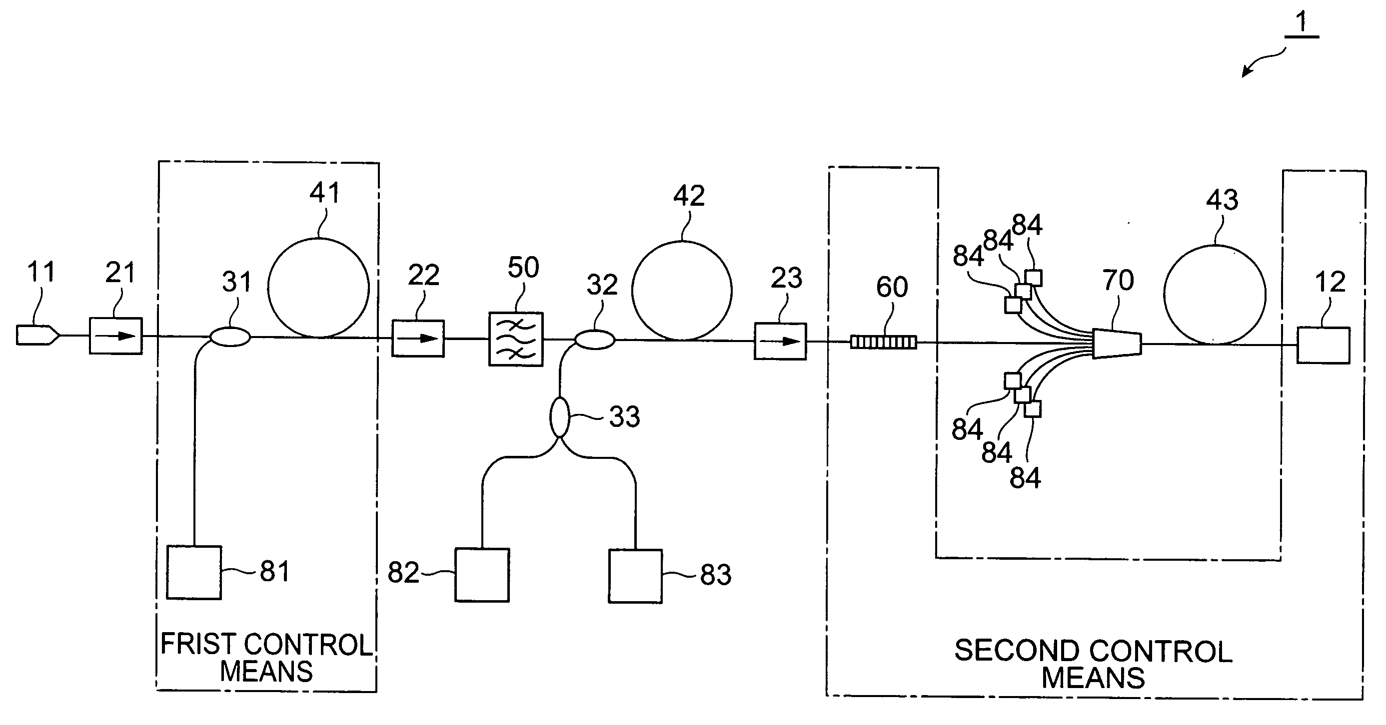
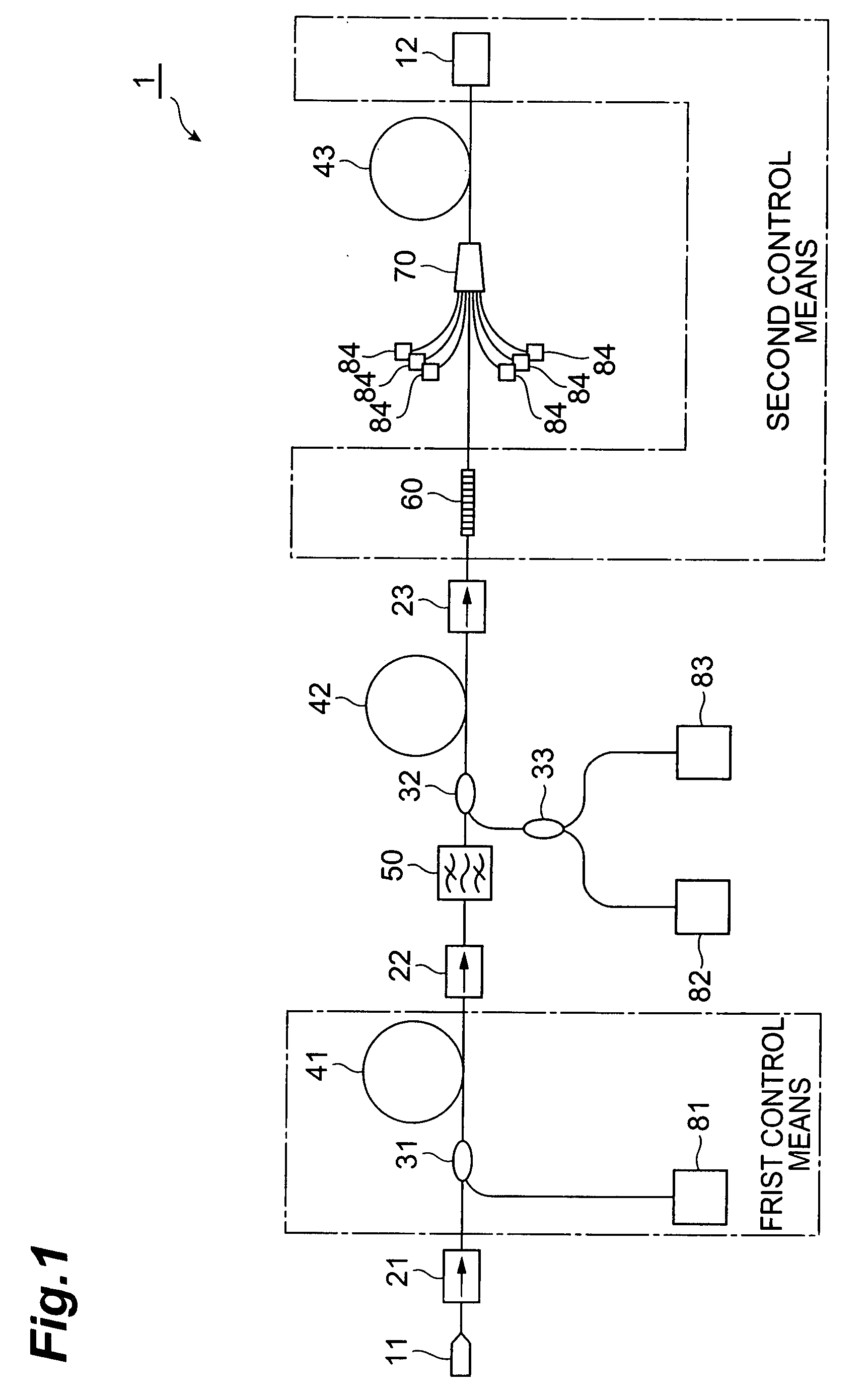
[0032]FIG. 1 is a diagram showing the structure of a first embodiment of the optical fiber amplifying module according to the present invention. The optical fiber amplifying module 1 according to the first embodiment shown in FIG. 1 inputs light fed to an input connector 11 and outputs thus amplified light as collimated light from an output collimator 12. The optical fiber amplifying module 1 comprises an optical isolator 21, an optical coupler 31, a YbDF 41, an optical isolator 22, a bandpass filter 50, an optical coupler 32, a YbDF 42, an optical isolator 23, an optical fiber Bragg grating 60, a combiner 70, and a YbDF 43 which are successively arranged from the input connector 11 to the output collimator 12. The optical fiber amplifying module 1 further comprises a pumping light source 81 connected to the optical coupler 31, a polarization beam combiner 33 connected to the optical coupler 32, pumping light sources 82, 83, and a plurality of pumping light sources 84 connected to t...

second embodiment

[0059]FIG. 11 is a diagram showing the structure of a main part in a second embodiment of the optical fiber amplifying module according to the present invention. The basic structure of the optical fiber amplifying module 2 according to the second embodiment is the same as that of the above-mentioned optical fiber amplifying module 1 according to the first embodiment. However, the second embodiment differs from the first embodiment in that it further comprises a first control means feedback structure. FIG. 11 does not depict the structure on the downstream side of the bandpass filter 50, since it is the same as that in the optical fiber amplifying module 1 according to the first embodiment.

[0060]As mentioned above, it is desirable that the gain from the input connector 11 to the optical isolator 22 be not higher than about 15 dB. However, the input and output of light to be amplified having a low duty cycle are hard to monitor accurately. Therefore, the optical fiber amplifying modul...

third embodiment

[0063]FIG. 12 is a diagram showing the structure of a main part in a third embodiment of the optical fiber amplifying module according to the present invention. The basic structure of the optical fiber amplifying module 3 according to the third embodiment is also the same as that of the above-mentioned optical fiber amplifying module 1 according to the first embodiment. However, the first control means in the third embodiment differs from that in the above-mentioned first and second embodiments in that it comprises a structure which makes it possible to protect the pumping light source 81 without monitoring the signal light (light to be amplified) having a low duty cycle. As with FIG. 11, FIG. 12 does not depict the structure on the downstream side of the bandpass filter 50, which is the same as that in the optical fiber amplifying module 1 according to the first embodiment.

[0064]In the optical fiber amplifying module 2 according to the third embodiment, as shown in FIG. 12, the fir...


PUM


Abstract

The present invention relates to an optical fiber amplifying module equipped with a structure for stably attaining a high gain even when amplifying light having a low duty cycle. The optical fiber amplifying module comprises at least three amplification optical fibers successively arranged from an input connector to an output collimator. A bandpass filter is arranged between the first- and second-stage amplification optical fibers. Control means having a structure constituted by optically passive components alone or a feedback structure functions so as to render an upper limit to a gain for input light in the first-stage amplification optical fiber, thereby preventing the deterioration in performances such as destruction of the bandpass filter from occurring in optical components positioned on the upstream side of the final-stage amplification optical fiber.

Description

BACKGROUND OF THE INVENTION[0001]1. Field of the Invention[0002]The present invention relates to an optical fiber amplifying module which amplifies input light with an amplification optical fiber.[0003]2. Related Background Art[0004]Optical fiber laser light sources have been known as highly-reliable, small-size light sources, and their beam quality is favorable in particular since they have a waveguide structure. Therefore, the optical fiber laser light sources have been widespread in various uses such as processing in electronic / mechanical fields, medicine, measurement, and optical communications.[0005]In particular, optical fiber laser light sources of MOPA (Master Oscillation Power Amplifier) structure in which pulsed seed light outputted from a seed light source is amplified by an optical fiber amplifying module show no pulse width expansion under the influence of the delay in propagation due to the fiber length and the like as compared with currently prevailing light sources o...

Claims


Application Information

Patent Timeline
IPC IPC(8): H01S3/063
CPCH01S3/10007H01S3/06758H01S3/0078H01S3/0064H01S3/1618H01S3/094007H01S3/1001H01S3/13013
Inventor KAKUI, MOTOKI
Owner MEGAOPTO
Why Eureka
Try Eureka