Supercharge Your Innovation With Domain-Expert AI Agents!

Ball bearing with carbon-carbon cage for gas turbine engines

a technology of ball bearings and turbine shafts, which is applied in the direction of machines/engines, liquid fuel engines, mechanical equipment, etc., can solve the problems of increasing the potential for operation failure, compromising the reliability and efficiency of the bearing cage, and not being able to handle high loads

Inactive Publication Date: 2008-06-05
HAMILTON SUNDSTRAND CORP
View PDF10 Cites 9 Cited by
  • Summary
  • Abstract
  • Description
  • Claims
  • Application Information

AI Technical Summary

Benefits of technology

The invention is an improved ball bearing assembly for gas turbine engines that uses a carbon-carbon cage to maintain the space between the ball elements when subjected to high loads, heat, and long-term storage. This results in better performance and durability of the assembly.

Problems solved by technology

Long-term storage, excessive operational heat, or cage wear from induced loads may compromise such reliability and efficiency of the bearing cage.
These common materials typically are not able to handle the high loads, heat generation and long-term storage typical of single use systems, and if used in practice may increase the potential of an operational failure.
Accordingly, it is desirable to utilise ball bearings with an uncomplicated and inexpensive cage material that can withstand the high loads, heat generation and long-term storage typical of single use systems for supporting the rotating turbine machine to achieve a successful miniature gas turbine engine for such expendable aeronautical applications.

Method used


Image

  • Ball bearing with carbon-carbon cage for gas turbine engines
  • Ball bearing with carbon-carbon cage for gas turbine engines
  • Ball bearing with carbon-carbon cage for gas turbine engines

Examples


Embodiment Construction

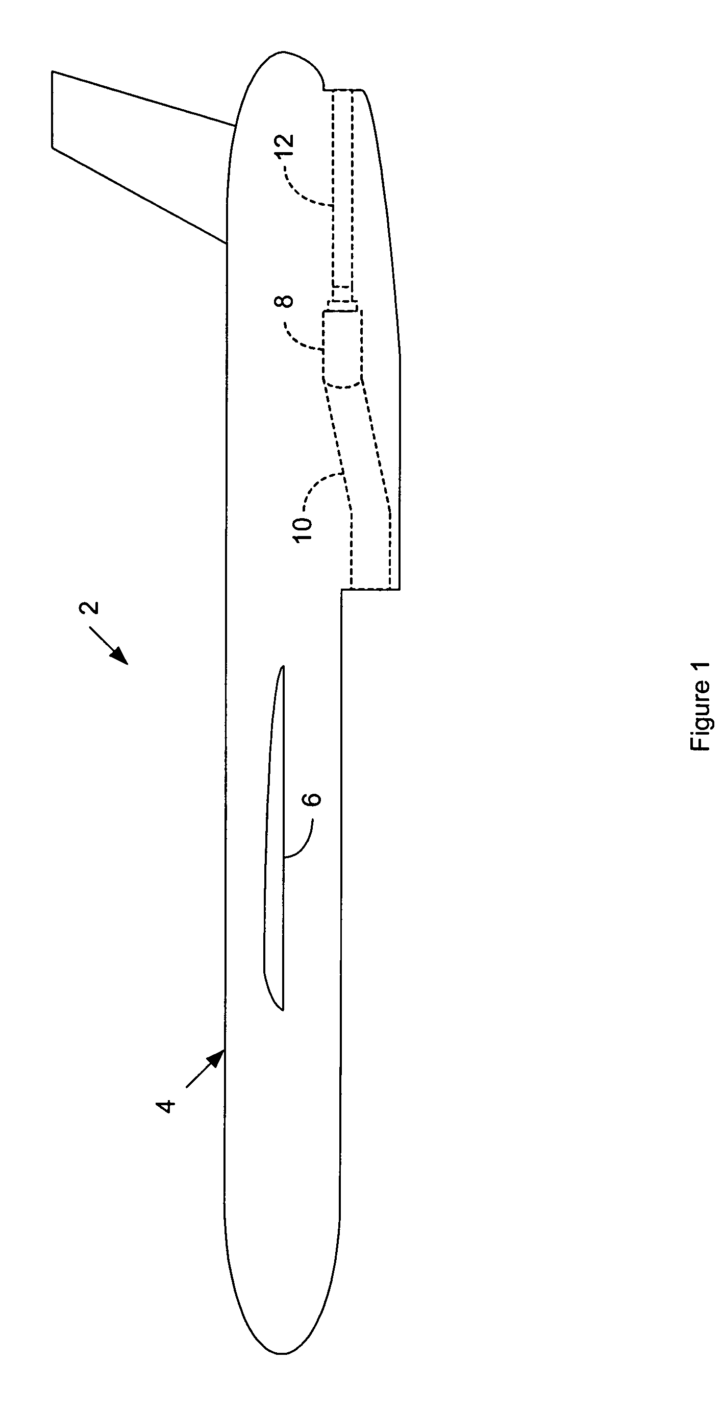
[0012]FIG. 1 is a side view of an expendable aeronautical vehicle 2 that is suitable for incorporating at least one embodiment of the invention. The vehicle 2 comprises an airframe 4 with one or more aerodynamic surfaces 6. The vehicle 2 also comprises a propulsion engine 8, typically of the gas turbine or turbojet type. The engine 8 mounts within or to the vehicle 2. In FIG. 1, for purposes of illustration the engine 8 mounts within the vehicle 2, as shown in dashed line. An intake 10, shown in dashed line, supplies ambient air to the engine 8. An exhaust pipe 12, shown in dashed line, exhausts the thrust of the engine 8 to propel the vehicle 2.

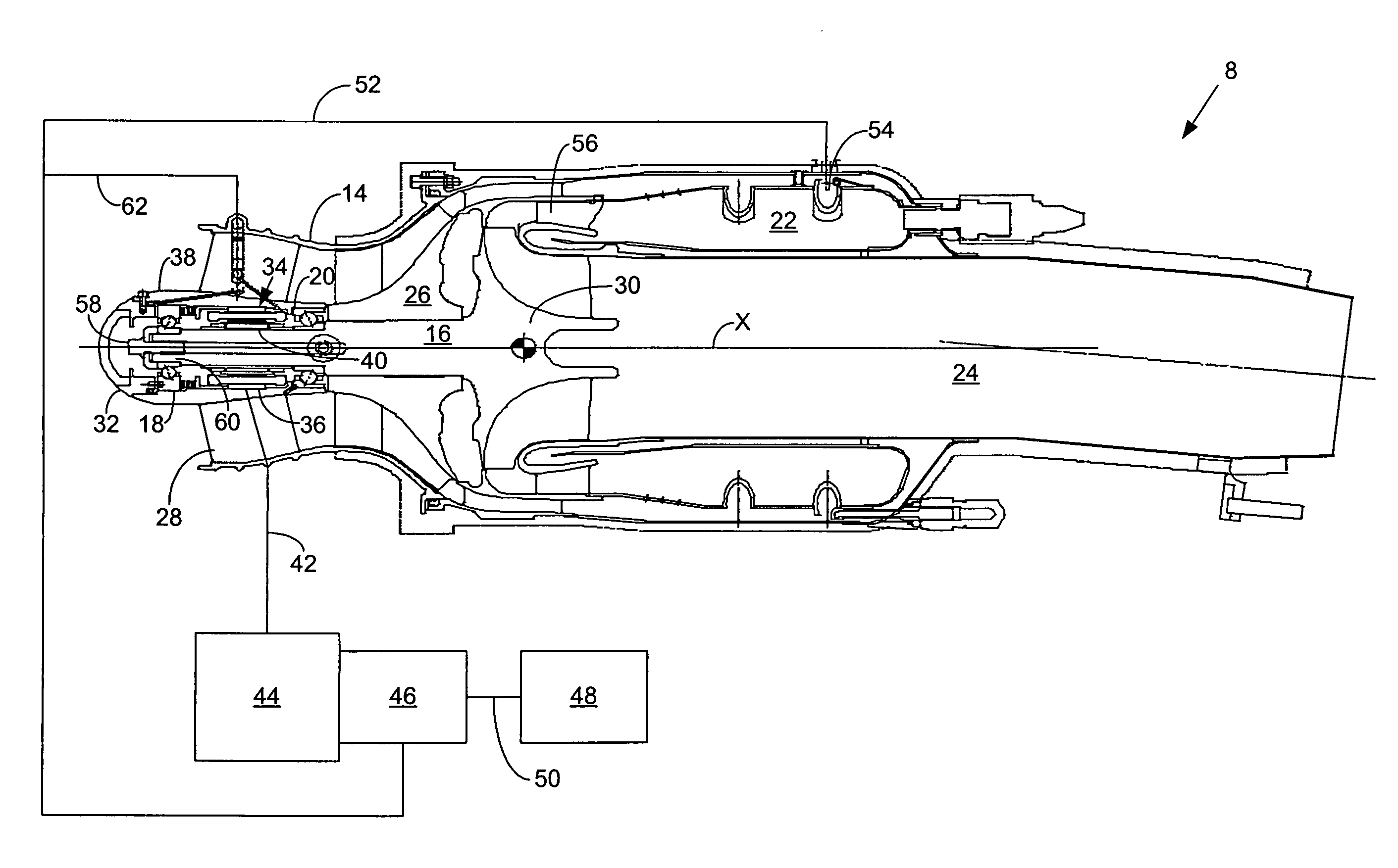
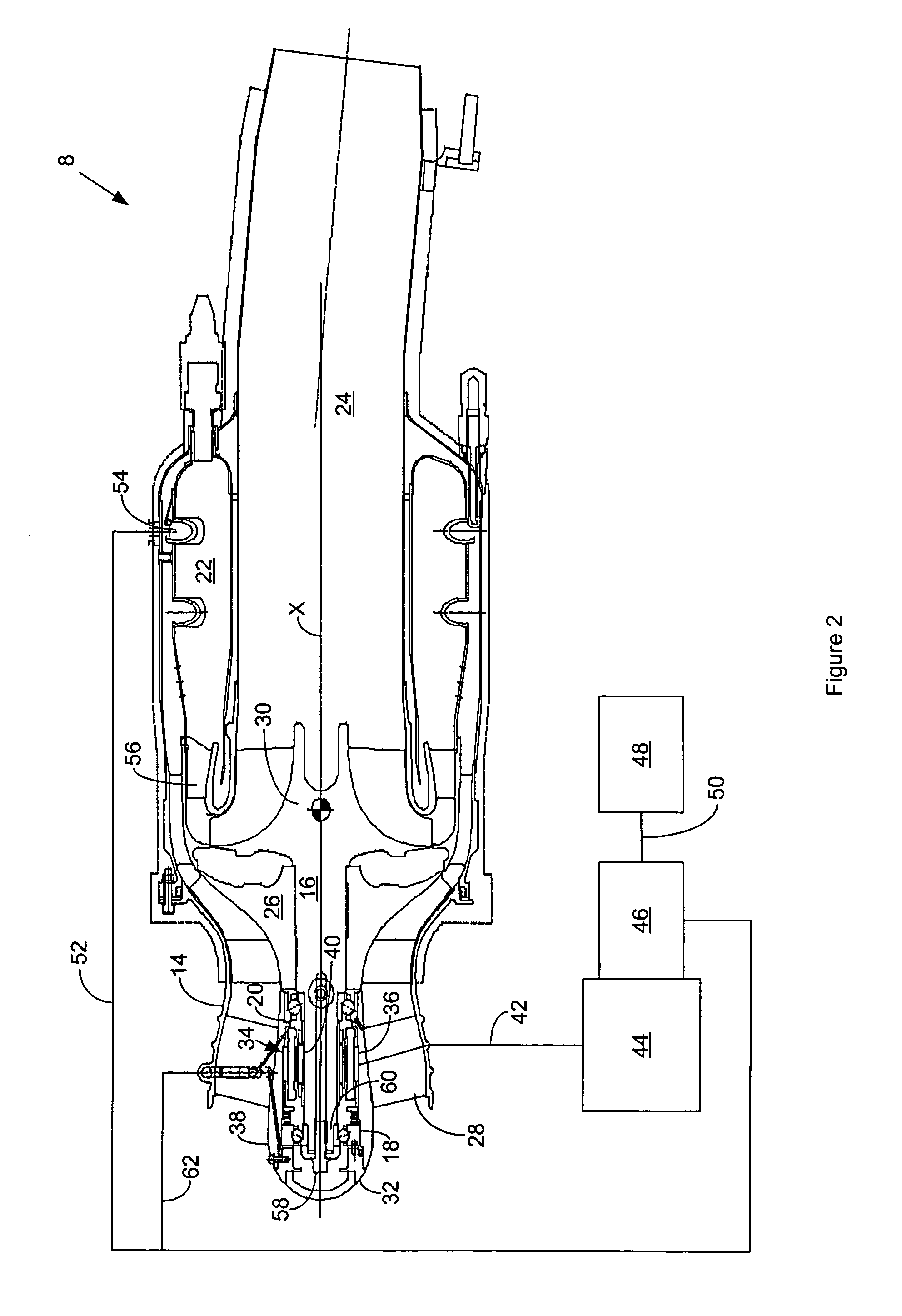
[0013]FIG. 2 is a cut-away side view of a miniature turbine engine 8 for the expendable aeronautical vehicle shown in FIG. 1 that is suitable for incorporating the invention. The miniature gas turbine engine 8 generally comprises a housing 14, a rotor shaft 16 supported by a forward bearing 18 and an aft bearing 20, a generally annular combu...


PUM


Abstract

A ball bearing assembly for a gas turbine engine comprises an inner race that couples to a rotor shaft; an outer race that couples to a primary static structural support; a plurality of ball elements between the inner race and the outer race; and a ball cage that comprises a carbon-carbon composite material to maintain the relative radial spacing of the ball elements between each other within the inner race and the outer race after subjection to high loads, heat generation and long-term storage.

Description

[0001]The invention occurred with government support under Contract No.: F08635-03-C0002 awarded by the United States Air Force. The government has certain rights in the invention.FIELD OF THE INVENTION[0002]The invention relates to bearings for gas turbine engines and more particularly to ball bearings for supporting a turbine shaft in a gas turbine engine.BACKGROUND OF THE INVENTION[0003]Miniature gas turbine or turbojet engines, typically of 150 lb-f thrust and smaller, are often useful for single-use airborne applications such as reconnaissance drones and other unmanned air and ground launched aeronautical vehicles. The use of such an engine greatly extends the range of such vehicles in comparison to the more conventional solid fuel rocket engine.[0004]A miniature gas turbine engine must have a relatively inexpensive manufacturing cost coupled with a high degree of starting and operational reliability when launched from air or ground systems in order to be an economically feasib...

Claims


Application Information

Patent Timeline
Patent Type & Authority Applications(United States)
IPC IPC(8): F01D25/16F16C33/44
CPCF16C33/44F16C2206/06F16C2360/23F16C33/6662
Inventor SHATZ, MARK N.JONES, ANTHONY C.ALEXANDER, ERIC J.JEWESS, GORDON F.
Owner HAMILTON SUNDSTRAND CORP
Features
  • R&D
  • Intellectual Property
  • Life Sciences
  • Materials
  • Tech Scout
  • Unparalleled Data Quality
  • Higher Quality Content
  • 60% Fewer Hallucinations
Learn More