Pusher sheath and deployment device

a technology of pusher rod and pusher sheath, which is applied in the direction of catheters, ear treatment, blood vessels, etc., can solve the problems of deployment device snags, the path to be followed by the deployment device is very tortuous, and the diameter section of the diameter section can be reduced, the effect of increasing flexibility

Inactive Publication Date: 2008-06-05
WILLIAM COOK EURO +1
View PDF14 Cites 36 Cited by
  • Summary
  • Abstract
  • Description
  • Claims
  • Application Information

AI Technical Summary

Benefits of technology

[0013]In the preferred embodiment, the reduced outer diameter section of the pusher member tapers towards the distal end thereof. It is preferred that this taper extends over a substantial distance, for example up to around 200 mm and in preferred embodiments up to around 150 mm. The advantage of having a reduced diameter section of this length is that it provides a substantial longitudinal extent of pusher member which has an increased flexibility compa

Problems solved by technology

However, problems can arise when the path to be followed by the deployment device is very tortuous.
In some instances, it is possible for the guidewire catheter to kink at its junction with the pusher sheath, with the result that the deployment device snags as the transition from the relatively

Method used


Image

  • Pusher sheath and deployment device
  • Pusher sheath and deployment device
  • Pusher sheath and deployment device

Examples


Embodiment Construction

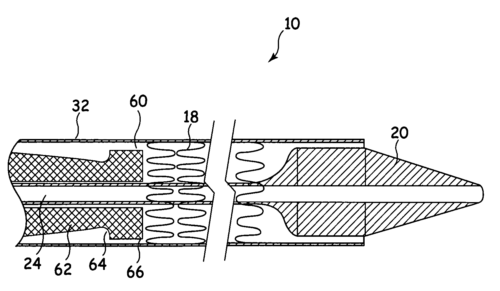
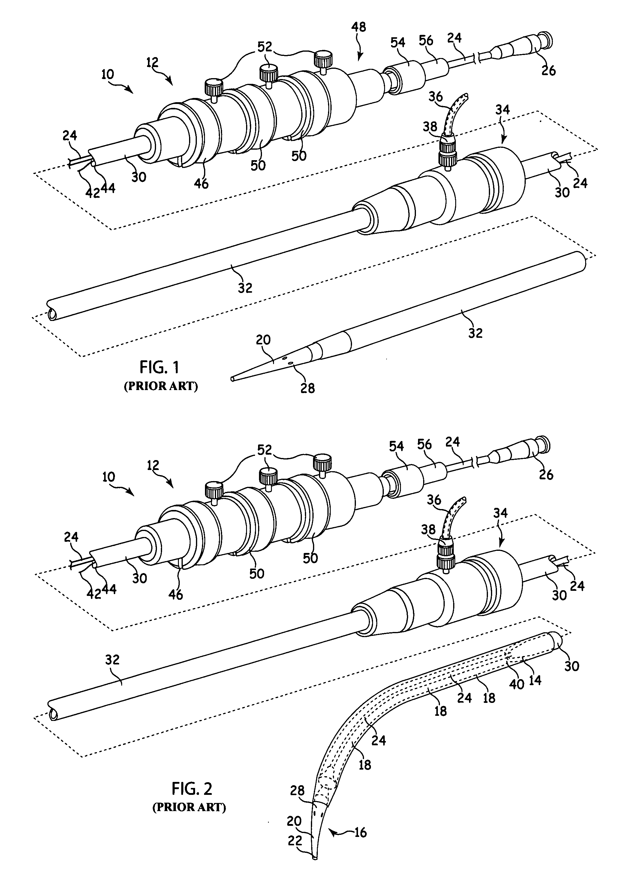
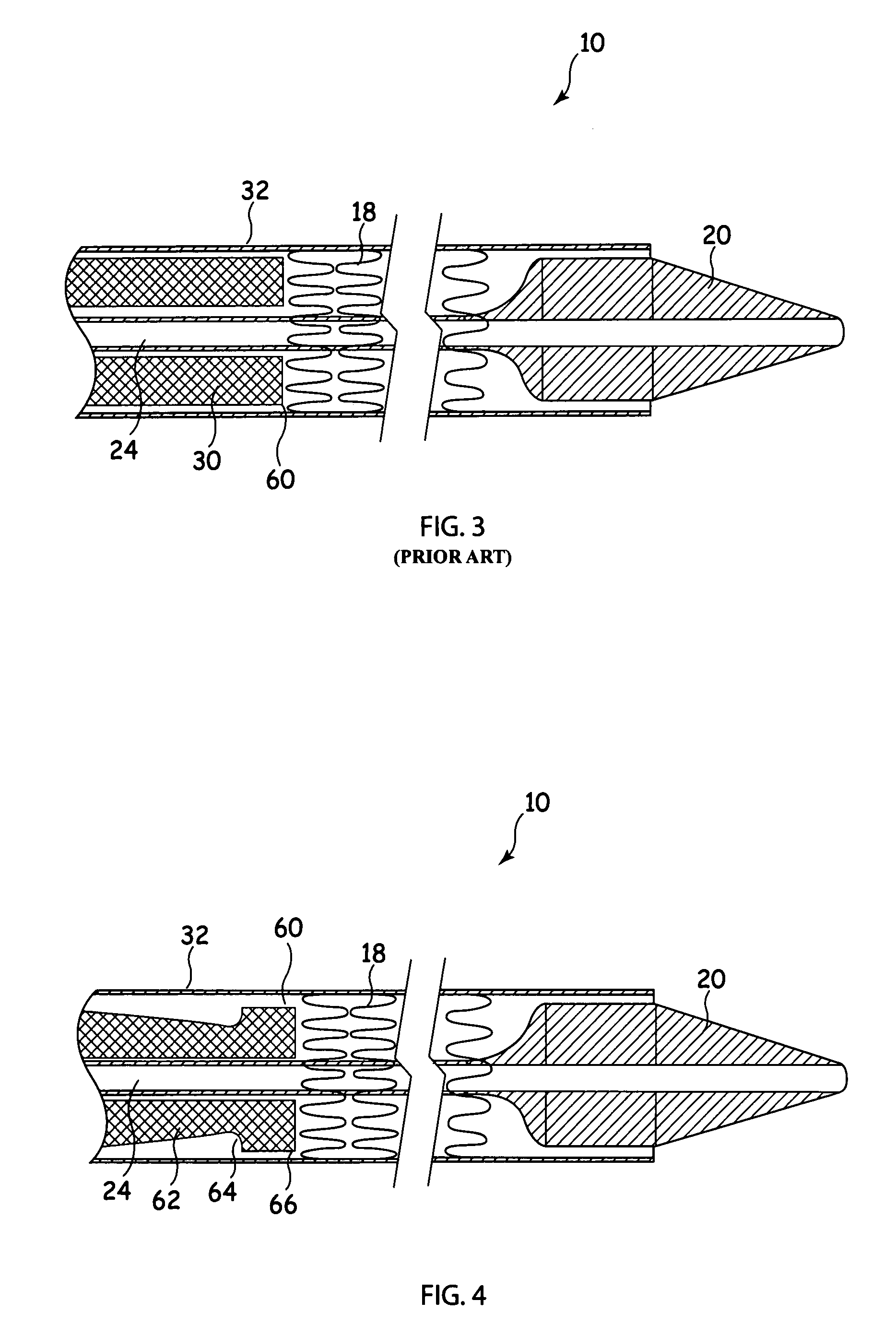
[0029]Referring to FIGS. 1 and 2, the introducer 10 includes an external manipulation section 12, a distal attachment region 14 and a proximal attachment region 16. The distal attachment region 14 and the proximal attachment region 16 secure the distal and proximal ends of the implant 18, respectively. During the medical procedure to deploy the implant 18, the distal and proximal attachment regions 14 and 16 will travel through the patient's lumen to a desired deployment site. The external manipulation section 12, which is acted upon by a surgeon to manipulate the introducer, remains outside of the patient throughout the procedure.

[0030]The proximal attachment region 16 of the introducer 10 includes a dilator tip 20, which is typically provided with a bore 22 therein for receiving a guide wire (not shown) of conventional type. The longitudinal bore 22 also provides a channel for the introduction of medical reagents. For example, it may be desirable to supply a contrast agent to allo...


PUM


Abstract

A stent or stent-graft deployment device and in particular a pusher member for such a device are disclosed. The pusher member ( 62 ) is provided with a reduced outer diameter section ( 64 ) and a pusher head ( 60 ). The reduced outer diameter section ( 64 ) reduces the thickness of the wall of the pusher member ( 62 ), with the result that the rigidity of the pusher member ( 62 ) is reduced at its distal end. This reduction in rigidity reduces the transition in flexibility between a guidewire catheter ( 24 ) extending through and beyond an inner channel of the pusher member ( 62 ) and the distal end of the pusher member ( 62 ). Thus, there is a gradual change in rigidities at the junction between these two components, which can reduce the possibility of kinking.

Description

CROSS-REFERENCE TO RELATED APPLICATIONS[0001]This application claims priority of provisional application Ser. No. 60 / 861,868, filed Nov. 30, 2006.TECHNICAL FIELD[0002]The present invention relates to a pusher sheath or pusher rod and deployment device including such a pusher sheath or rod. The pusher sheath is intended for use in delivering stents, stent grafts and other devices typically delivered by percutaneous delivery methods well known in the art.BACKGROUND OF THE INVENTION[0003]Deployment devices for deploying stents, stent grafts and other intra luminal devices typically include: a guidewire, a guidewire catheter, an insert support (which may be a portion of the guidewire catheter), a pusher sheath or rod, a proximal manipulation unit, as well as various other components well known in the art. The guidewire, which is typically provided with radio opaque markings or other markers, is typically made of a very flexible metal or metallic material and is introduced before the oth...

Claims


Application Information

Patent Timeline
IPC IPC(8): A61F2/06
CPCA61M25/008A61F2/95A61F2/966
Inventor RASMUSSEN, ERIK E.
Owner WILLIAM COOK EURO
Why Eureka
Try Eureka