

Electromagnetic Variable Transmission
- Summary
- Abstract
- Description
- Claims
- Application Information
AI Technical Summary
Benefits of technology
Problems solved by technology
Method used
Image

Examples
Embodiment Construction
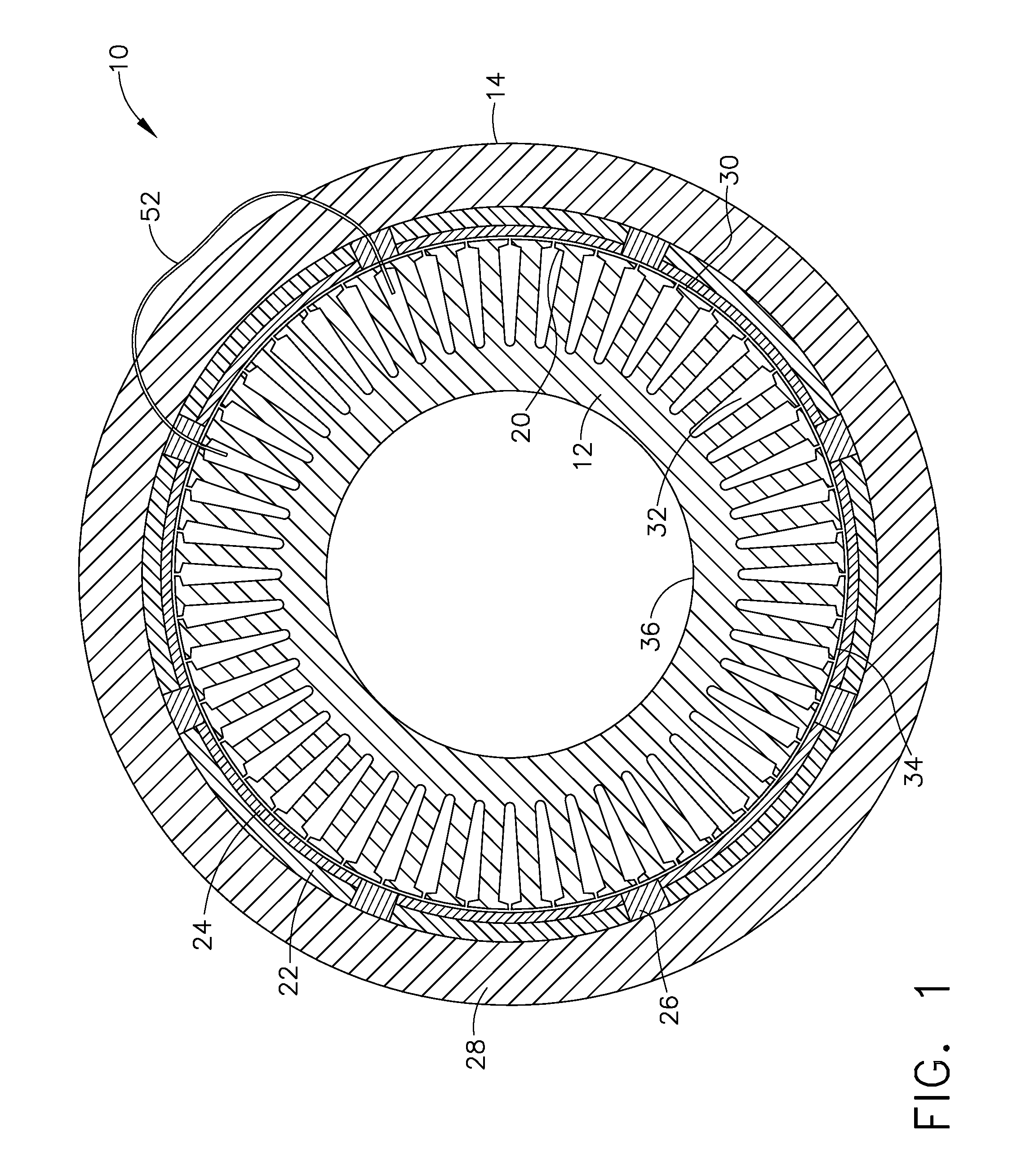
[0030]Referring to FIG. 1, an electromagnetically variable transmission (EVT) 10 includes two rotating components, an inner rotor 12 and an outer rotor 14. Both the inner rotor 12 and the outer rotor 14 rotate in the same direction around a common axis 16. The outer rotor 14 has multiple permanent magnet pole pairs 18 facing the outer surface 34 of the inner rotor 12. The magnets of the pole-pairs 18 are oriented in alternating fashion, such that one magnet of the pair has its north pole directed radially outwards and the adjacent magnet has its south pole directed radially inwards. An optional pole cap 24 may be attached on the top of each magnet segment 22 to reduce losses induced in the magnets due to flux slot harmonics inside the magnets 22 when there is a large difference between the rotational velocity of the inner rotor 12 and the outer rotor 14. The pole caps 24 may be laminated stack, soft magnetic composite material, or other magnetically permeable material suitable to fo...
PUM
 Abstract
Description
Claims
Application Information