

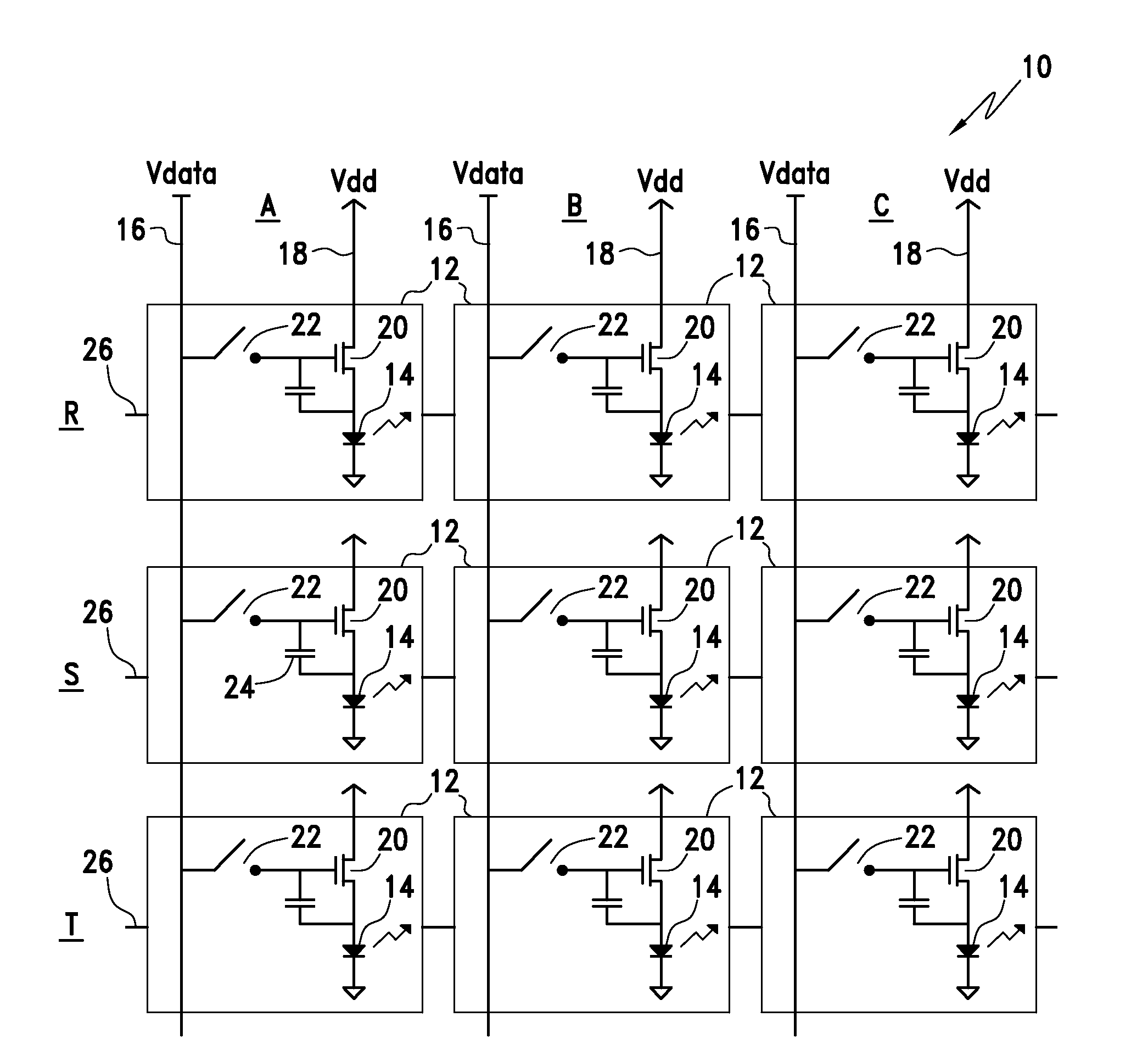
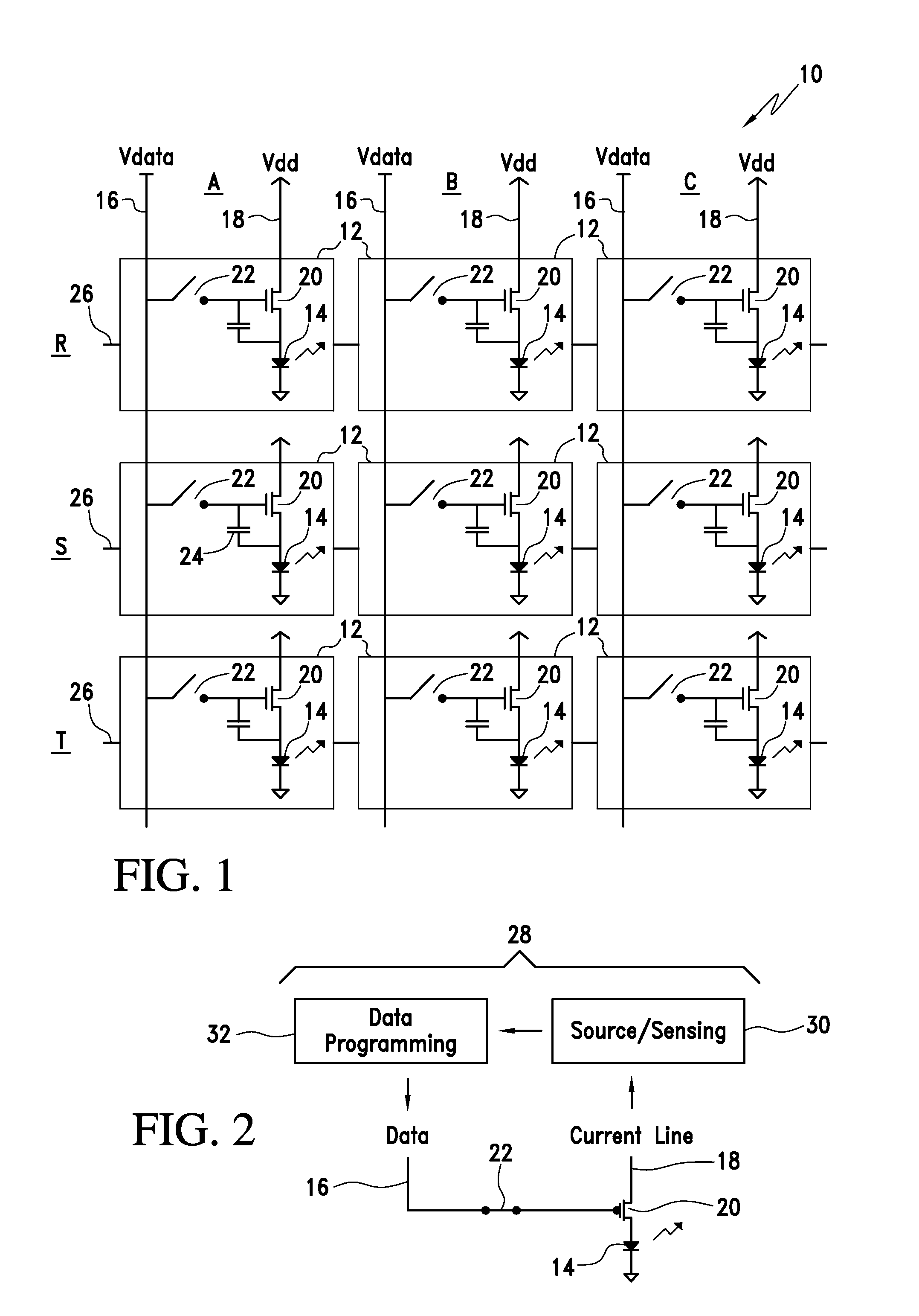
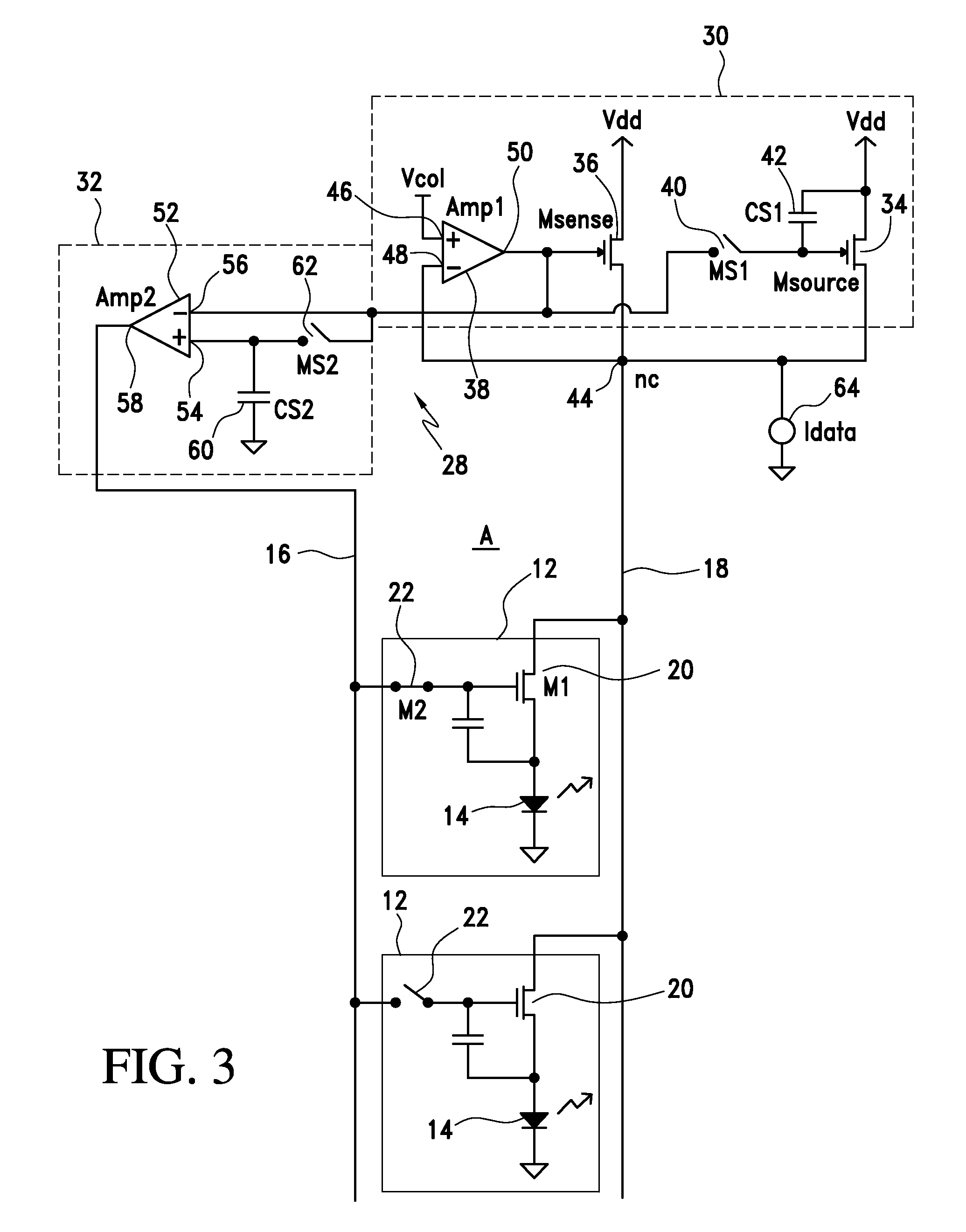
Active matrix display and method
- Summary
- Abstract
- Description
- Claims
- Application Information
AI Technical Summary
Benefits of technology
Problems solved by technology
Method used
Image

Examples
example 1
[0040]A circuit simulation was performed with PSPICE® computer software. PSPICE® is computer software for analog and mixed analog / digital circuit simulation and is provided by ORCAD, Inc., 2655 Seely Avenue, San Jose, Calif. 95134 through EMA Design Automation, Inc., PO Box 23325, Rochester, N.Y. 14692. PSPICE® software accepts user input circuit schematics and transistor models and addressing information and generates a simulated response.
[0041]A circuit schematic was PSPICE® simulated to substantially match the FIG. 2 and FIG. 3 circuits. The signals represented in FIG. 4 are the control signals that activated the different switches in the display driver; in particular, the voltage signals that controlled MS1, MS2 and transistor M2 in the pixel being programmed. The FIG. 5 output graph represents current though the programmed pixel as a function of time as well as the data current as a function of time (Idata 64 feed to node nc of the display driver).
[0042]Simulated system variabl...
example 2
[0045]The following EXAMPLE was set up to compare programming of data current in display pixels with drive transistors, M1 with different properties and to demonstrate this function at different column current levels.
[0046]A display driver for a display column was fabricated in single crystal silicon integrated circuits (ICs). The column included test pixel circuits implemented in the IC as well. The test pixel circuits were fabricated to have identical properties except for M1 transistor size. Two pixels were fabricated with a size difference of 20% in the width of M1 to emulate 20% mobility differences. In order to emulate threshold voltage variations, an external v voltage source was connected to the pixel. This voltage source represented a change of 25% to the threshold of transistor M1.
[0047]In the procedures, LabVIEW® computer software was used to apply circuit voltages. LabVIEW® computer software is used to control and emulate scientific and engineering instruments and instru...
PUM
 Abstract
Description
Claims
Application Information