Phase locked loop with adaptive phase error compensation

a phase error compensation and phase lock technology, applied in the direction of electrical equipment, pulse automatic control, etc., can solve the problems of incompatibility of frequency resolution normally obtained by the pre-divider, output jitter, and more vco nois

Active Publication Date: 2008-06-12
CADENCE DESIGN SYST INC
View PDF9 Cites 24 Cited by
  • Summary
  • Abstract
  • Description
  • Claims
  • Application Information

AI Technical Summary

Benefits of technology

[0011]This disclosure describes various embodiments for new PLL designs that address one or more of the above-described needs. The present disclosure also describes novel PLL designs that allow very accurate fractional divisions and do not suffer from the accuracy limitations of conventional DAC compensation and do not inject other tonal anomalies such as those of the delta-sigma approach.

Problems solved by technology

However, in an integer-N PLL, the requirement of frequency resolution normally obtained by the pre-divider become incompatible with jitter requirements which dictate loop bandwidth necessary to suppress VCO noise.
However, the operation of fractional-N PLL usually causes in-band frequency spurs as shown in FIG. 4, which manifests itself in output jitter and is undesirable.
To suppress spurs in the classical fractional-N PLLs, the only recourse is to reduce the loop bandwidth, which would result in more VCO noise.
These tones can be removed by adding dither, which, however, would add design complexity to an already complex system.
Although higher order modulators can be used to reduce the idle tone generation by increasing the chaotic energy which busts up the tonal energy, higher order modulators require steeper transition loop filters which in turn affect phase margin and stability.
However, the MASH delta-sigma approach suffers from similar tonal problems.
Dithering may be employed to suppress the tonal generation but this introduces more complexity into an already complex system.

Method used


Image

  • Phase locked loop with adaptive phase error compensation
  • Phase locked loop with adaptive phase error compensation
  • Phase locked loop with adaptive phase error compensation

Examples


Embodiment Construction

[0029]In the following description, for the purposes of explanation, numerous specific details are set forth in order to provide a thorough understanding of the present disclosure. It will be apparent, however, to one skilled in the art that the present disclosure may be practiced without these specific details. In other instances, well-known structures and devices are shown in block diagram form in order to avoid unnecessarily obscuring the present disclosure.

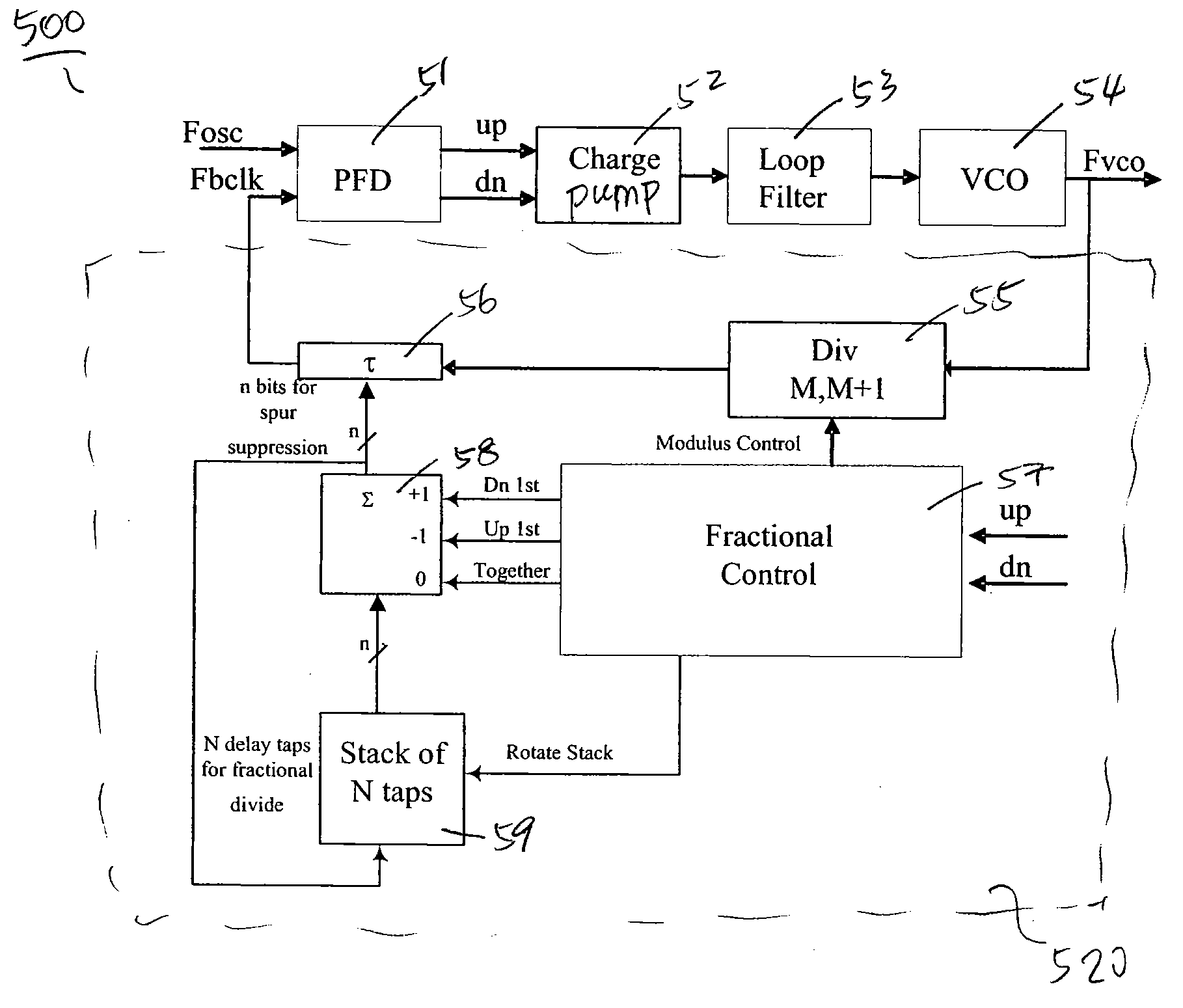
[0030]FIG. 5 shows a block diagram of an exemplary PLL 500 according to this disclosure. In FIG. 5, a phase-frequency comparator (PFD) 51 receives a reference signal Fosc and a feedback signal Fbclk generated by a feedback loop. The PFD 50 detects a phase error between the reference signal Fosc and the feedback signal Fbclk, and outputs pulse signals UP and DN corresponding to the phase error. A charge pump 52 generates a charge pump output current in response to the pulse signals UP and DN, and sends the charge pump output cu...


PUM


Abstract

An adaptive phase-locked loop (PLL) circuit produces an output signal having a frequency in reference to the frequency of a reference signal. The PLL circuit includes an oscillator configured to generate the output signal according to a frequency control signal, and a processing circuit configured to generate a feedback signal deriving from the output signal. An adjustable shift circuit is provided to time-shift the feedback signal. The PLL further includes a phase comparison circuit configured to generate a phase error signal indicating a phase error between the time-shifted feedback signal and the reference signal, and a control circuit configured to generate the frequency control signal based on the phase error signal. The adjustable shift circuit adjusts a time-shift amount to time-shift the feedback signal according to the phase error signal.

Description

FIELD OF THE DISCLOSURE[0001]The present invention relates to a phase locked loop (PLL), and more particularly, to a phase locked loop circuit with adaptive phase error compensationBACKGROUND OF THE INVENTION[0002]A frequency synthesizer is an apparatus that generates an output signal having a frequency that is an exact multiple of a reference frequency. The accuracy of the output signal frequency is typically determined by the accuracy and stability of the reference frequency source.[0003]A common type of frequency synthesizer uses a phase-locked loop (PLL) to provide an output signal having a selectable, precise and stable frequency. The PLL includes a phase detector, a voltage-controlled oscillator (VCO) and a feedback path arranged in a way that the phase of the VCO output is forced to be synchronous with the phase of the input reference frequency. FIG. 1 is a circuit diagram showing a configuration of a conventional integer-N phase locked loop (PLL) circuit having an integer fr...

Claims


Application Information

Patent Timeline
Patent Type & Authority Applications(United States)
IPC IPC(8): H03L7/089H03L7/08H03L7/085
CPCH03L7/081H03L7/1976H03L7/0891
Inventor HUFFORD, MICHAEL M.NAVIASKY, ERICCAVIGLIA, TONY
Owner CADENCE DESIGN SYST INC
Why Eureka
Try Eureka