Al technical title is built by PatSnap Al team. It summarizes the technical point description of the patent document.
a technology of occlusion and apparatus, applied in the field of guidewire systems, can solve the problems of myocardial infarction or heart attack, initial guidewire placement is difficult or impossible in tortuous regions of the vasculature, and is equally difficul
Inactive Publication Date: 2008-06-12
BOSTON SCI SCIMED INC
View PDF99 Cites 98 Cited by
Summary
Abstract
Description
Claims
Application Information
AI Technical Summary
This helps you quickly interpret patents by identifying the three key elements:
Problems solved by technology
Method used
Benefits of technology
[0010]By way of example, and not limitation, it was found that while a deflection angle is advantageous to allow the user to torque the guidewire to re-direct the tip, as the deflection angle increases the axial penetration force decreases. The pre-determined fixed deflection of the distal end of the guidewire body according to the present invention, ranges from about 0° to about 90 degrees (“°”), from about 0° to about 60°, from about 5° to about 45°. In an embodiment, the pre-determined fixed deflection is about 15°, about 30°, or about 45°. The fixed deflection of the distal end of the hollow guidewire body may be arrived at in a smooth transition or in an abrupt transition, or any type and degree of transition inbetween. To facilitate passing through the occlusion or stenosis, the distal end of the hollow guidewire can be steerable to provide better control of the creation of the path through the occlusion or stenosis. Optionally, the target site can be infused and / or aspirated before, during, and after creation of the path through the occlusion.
[0036]Electronic circuitry within the control system of the handle may measure a variety of characteristics for feedback control. For instance, the load encountered during advancement of the distal tip in the body lumen may be measured. For example, a load sensor may be coupled to the motor and configured to provide an output representative of the load on the motor. In an embodiment, an audible and / or visual output may be coupled to the load sensor to provide load status to the user. The audio feedback may be represented in a continuous spectrum or it may be represented as a plurality of discrete load levels. The visual feedback may be represented as a plurality of discrete load levels. In another embodiment, absence of load may be indicative of a break or fracture in the oscillating drive shaft distal tip. A locking mechanism on a distal end of the guidewire body may be provided to further prevent inadvertent release of the distal tip of the drive shaft into the body lumen by locking it to a distal end of the hollow guidewire. Still further, the device may be automatically disabled in response to the no load measurement as an added safety feature. In still another instance, a use of the device based on time or number of revolutions or oscillations may be measured. The device may be automatically and permanently disabled once the measured time or number is above a threshold value. This safety feature protects against device fatigue and warrants that the device is not operable past its optimal lifetime use.
Problems solved by technology
Atheromatous and other vascular deposits restrict blood flow and can cause ischemia which, in acute cases, can result in myocardial infarction or a heart attack.
Initial guidewire placement, however, can be difficult or impossible in tortuous regions of the vasculature.
Moreover, it can be equally difficult if the lesion is total or near total, i.e. the lesion occludes the blood vessel lumen to such an extent that the guidewire cannot be advanced across the lesion.
Method used
Image
Click on the blue label to locate the original text in one second.
Reading with bidirectional positioning of images and text.
Examples
Embodiment Construction
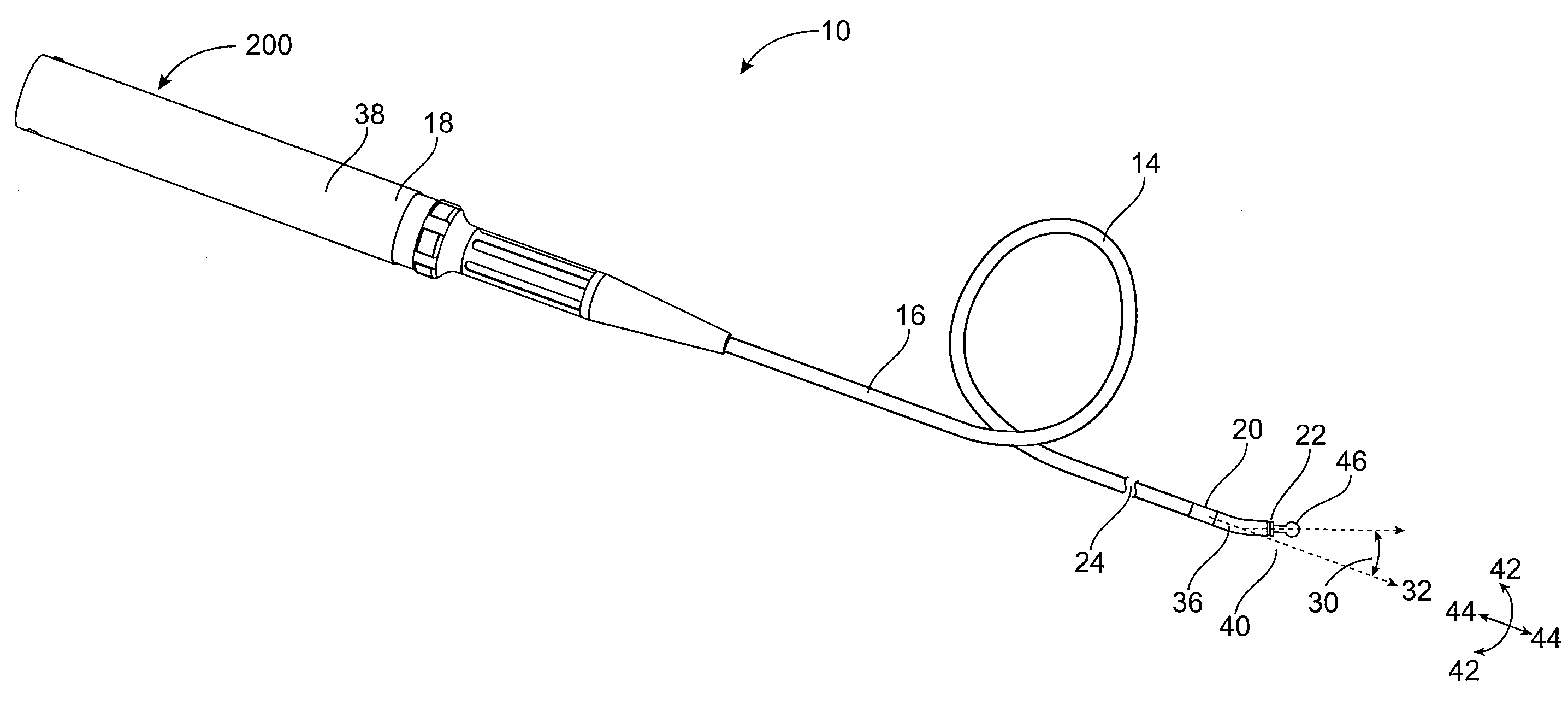
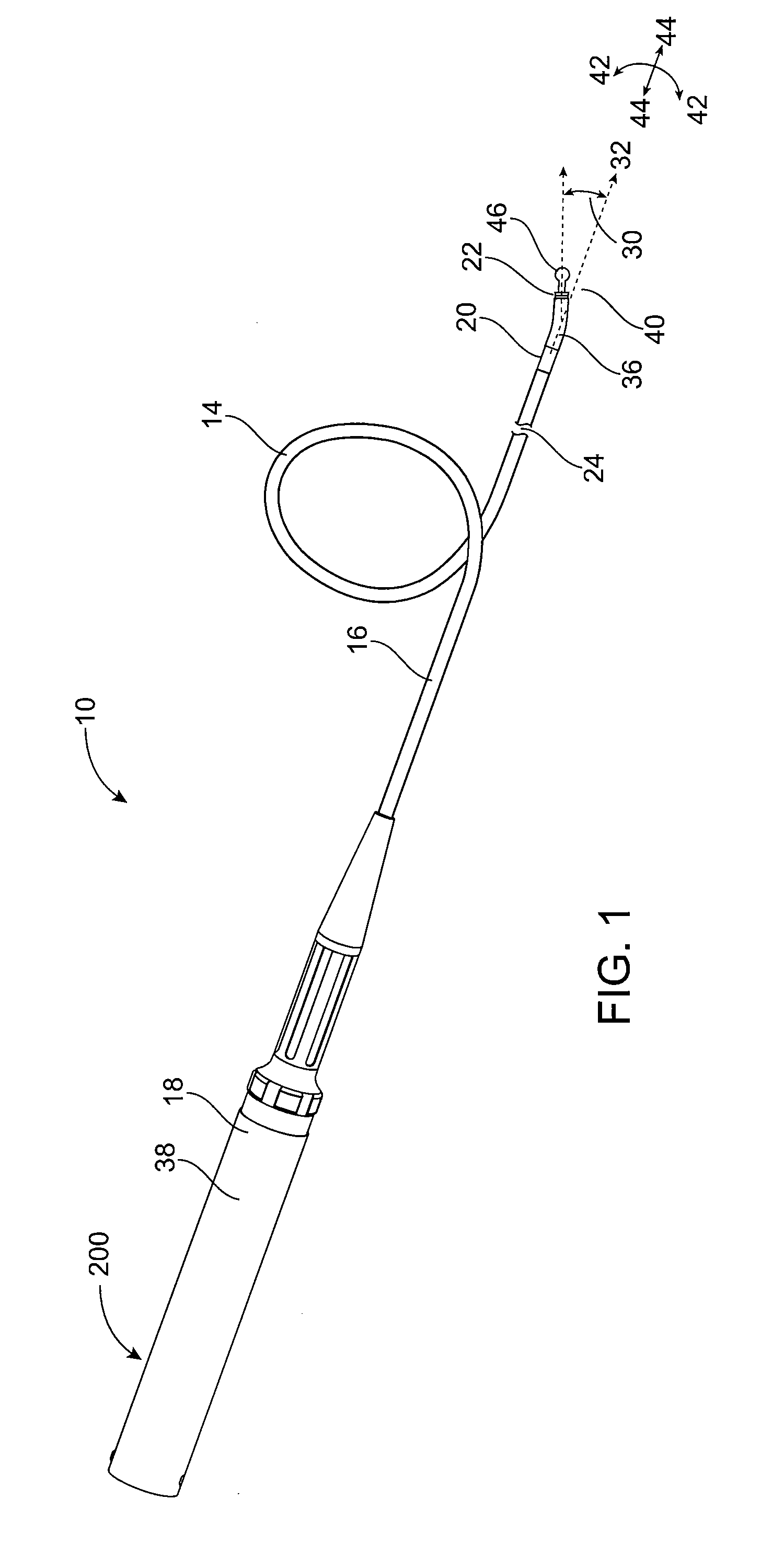
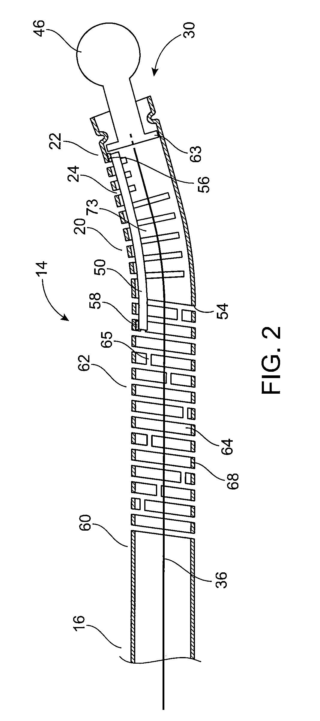
[0051]The systems, devices and methods according to the present invention will generally be adapted for the intraluminal treatment of a target site within a body lumen of a patient, usually in a coronary artery or peripheral blood vessel which is occluded or stenosed with atherosclerotic, stenotic, thrombotic, or other occlusive material. The systems, devices and methods, however, are also suitable for treating stenoses of the body lumens and other hyperplastic and neoplastic conditions in other body lumens, such as the ureter, the biliary duct, respiratory passages, the pancreatic duct, the lymphatic duct, and the like. Neoplastic cell growth will often occur as a result of a tumor surrounding and intruding into a body lumen. Removal of such material can thus be beneficial to maintain patency of the body lumen. While the remaining discussion is directed at passing through atheromatous or thrombotic occlusive material in a coronary artery, it will be appreciated that the systems and...
PUM
Abstract
A torqueable hollow device, such as a hollow guidewire device, with a pre-determined fixed distal tip is disclosed for removing occlusive material and passing through occlusions, stenosis, thrombus, plaque, calcified material, and other materials in a body lumen, such as a coronary artery. The hollow guidewire generally comprises an elongate, tubular guidewire body that has an axial lumen. A mechanically moving core element is positioned at or near a distal end of the tubular guidewire body and extends through the axial lumen. Actuation of the core element (e.g., oscillation, reciprocation, and / or rotation) creates a passage through the occlusive or stenotic material in the body lumen.
Description
CROSS-REFERENCES TO RELATED APPLICATIONS[0001]The present application is related to U.S. patent application Ser. No. 09 / 030,657, Attorney Docket No. 019635-000100US, filed Feb. 25, 1998, entitled “Steerable Unitary Infusion Catheter / Guide Wire Incorporating Detachable Infusion Port Assembly,” and now U.S. Pat. No. 6,059,767, and U.S. patent application Ser. No. 09 / 935,534, Attorney Docket No. 019635-000310US, filed Aug. 22, 2001, entitled “Steerable Support System with External Ribs / Slots that Taper,” and now U.S. Pat. No. 6,746,422, the complete disclosures of which are incorporated herein by reference, in their entirety. The present application is also related to U.S. patent application Ser. No. 11 / 236,703, Attorney Docket No. 019635-000240US, filed Sep. 26, 2005, entitled “Guidewire for Crossing Occlusions or Stenoses,” which was a continuation-in-part of U.S. patent application Ser. No. 10 / 999,457, Attorney Docket No. 019635-000500US, filed Nov. 29, 2004, entitled “Guidewire For...
Claims
Application Information
Patent Timeline
Application Date:The date an application was filed.
Publication Date:The date a patent or application was officially published.
First Publication Date:The earliest publication date of a patent with the same application number.
Issue Date:Publication date of the patent grant document.
PCT Entry Date:The Entry date of PCT National Phase.
Estimated Expiry Date:The statutory expiry date of a patent right according to the Patent Law, and it is the longest term of protection that the patent right can achieve without the termination of the patent right due to other reasons(Term extension factor has been taken into account ).
Invalid Date:Actual expiry date is based on effective date or publication date of legal transaction data of invalid patent.
Patent Type & Authority Applications(United States)
IPC IPC(8): A61B17/22
CPCA61B2017/003A61B17/320758A61B2017/320028
Inventor CARLEY, MICHAELCHECHELSKI, VICTORSUDARIA, RUDOLFOAGANON, NESTORHUYNH, CHRISTOPHERNORIEGA, GERARDO V.