
Bypass vascular graft

a technology of bypass vascular graft and vascular bypass, which is applied in the field of vascular bypass graft, can solve problems such as graft failure, and achieve the effect of improving blood flow and preventing clotting

Active Publication Date: 2008-06-12
BATISTE STANLEY
View PDF7 Cites 3 Cited by
  • Summary
  • Abstract
  • Description
  • Claims
  • Application Information

AI Technical Summary

Benefits of technology

[0010]A vascular bypass graft is disclosed which improves blood flow in an occluded region of a patient's vascular system by providing an alternate route for blood to flow. In one embodiment the vascular bypass graft has a primary graft member through which the blood flow is primarily directed, and an outflow limb or secondary graft member through which circulation of blood through the graft can be maintained to prevent clotting.
[0011]The circulation of blood through the secondary graft member has the advantage of maintaining a high blood flow rate in conditions where there would ordinarily be a low blood flow rate. The high flow rate prevents blood clots which would occlude the graft and lead to graft failure as often seen in known bypass grafts.
[0012]Generally, the graft utilizes an adjustable or fixed blood flow restrictor which is used in conjunction with the outflow limb member to control amount of blood circulation and pressure within the bypass graft. This allows the bypass graft to be customized to a particular patient and allows the flow rate to be changed as medical conditions or other factors dictate. In addition, the adjustable configurations of the invention allow changes to flow rate automatically and without further surgery.
[0013]In one embodiment, the primary graft member has openings on both its ends, one to allow the flow of blood into the vascular bypass graft and the other to allow the flow of blood to continue past an occlusion and back out to the vascular system. Near the end where blood flows back to the vascular system is attached the secondary graft member through which another flow of blood is circulated back to the vascular system. This circulation prevents clotting within the graft.
[0014]The primary and secondary graft members may be formed in various ways. In one embodiment they are integrally formed so as to share a single main body. In another embodiment the secondary member is flared out at the point it is attached to the vascular system. In yet another embodiment, the secondary graft member may include a stenosis restrictor which can control pressure and flow within the graft by reducing or even blocking the flow of blood through the secondary graft member.

Problems solved by technology

The high flow rate prevents blood clots which would occlude the graft and lead to graft failure as often seen in known bypass grafts.

Method used


Image

  • Bypass vascular graft
  • Bypass vascular graft
  • Bypass vascular graft

Examples


Embodiment Construction

[0036]In the following description, numerous specific details are set forth in order to provide a more thorough description of the present invention. It will be apparent, however, to one skilled in the art, that the present invention may be practiced without these specific details. In other instances, well-known features have not been described in detail so as not to obscure the invention.

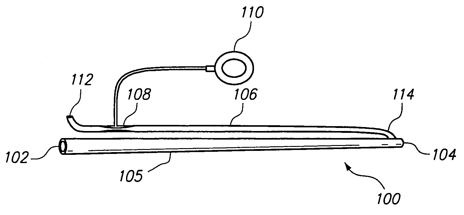
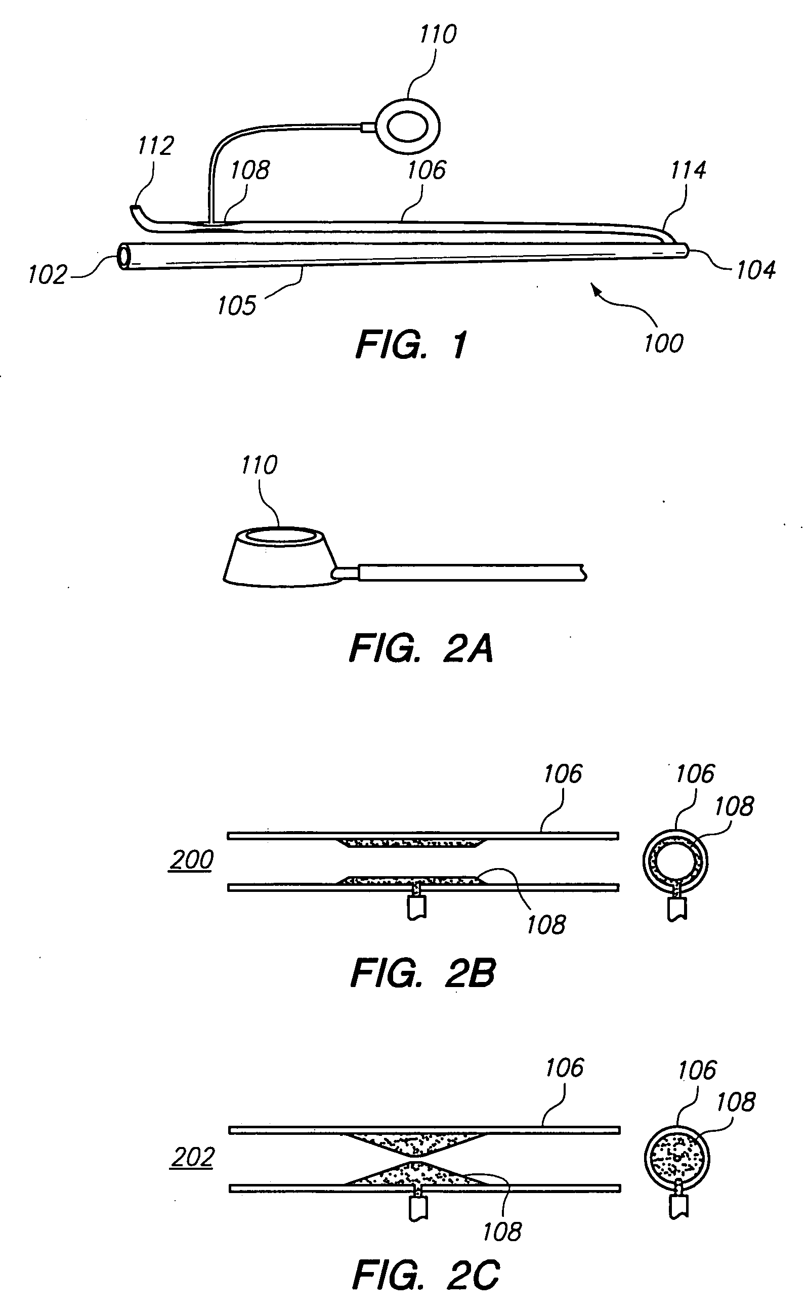
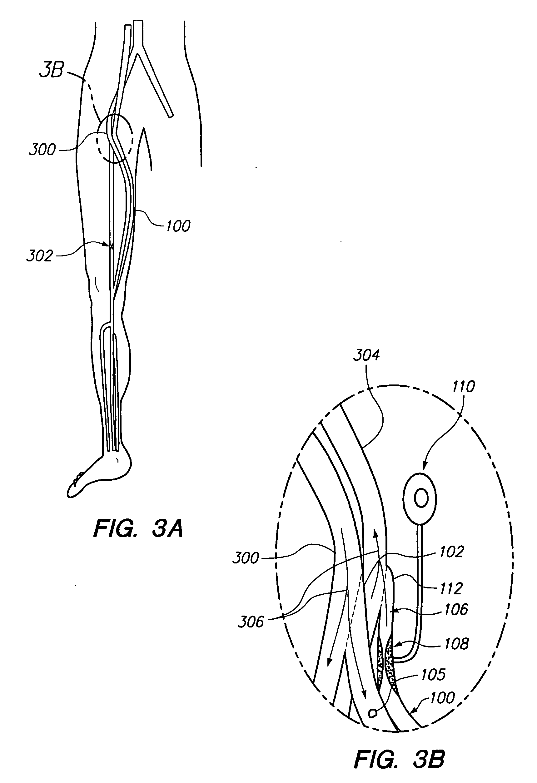
[0037]The primary reason for the formation of blood clots in a bypass graft is that the blood flow through the graft is of such low velocity that blood clotting mechanisms are triggered. Regions of low velocity blood flow are common in the body's smaller vessels such as veins and capillaries. Low velocity regions are also found in the transitions between larger vessels, such as arteries, to smaller ones, such as veins or capillaries because the reduction in size reduces flow capacity and thus blood flow velocity is also reduced. Thus, if a bypass graft is attached to a small vessel at its outflow e...


PUM


Abstract

A vascular bypass graft having a primary member and a secondary member is disclosed. The secondary member extends from a distal second end of the primary member and has a common fluid pathway there between. The secondary member may have a flared or diffused proximal first end that facilitates low pressure fluid return and may be integrally formed with the primary member. An adjustable or fixed stenosis is provided in the secondary member which allows the fluid flow through the vascular bypass graft to be modified. The stenosis may be adjusted either manually or by way of a controller. The primary member is surgically connected to a patient's vascular system to provide an alternate route for blood flow around a vascular occlusion. The secondary member is surgically connected to another point in the vascular system to allow continuous circulation of blood through the graft thereby preventing clotting and graft failure.

Description

1. CROSS-REFERENCE TO RELATED APPLICATIONS[0001]This application claims priority to U.S. Provisional Patent Application No. 60 / 873,788 filed on Dec. 7, 2006 titled IMPROVED BYPASS VASCULAR GRAFT.BACKGROUND OF THE INVENTION[0002]1. Field of the Invention[0003]The present invention relates to vascular bypass grafts and, in particular, to surgically implanted grafts which increase blood flow and reduce clotting.[0004]2. Related Art[0005]Vascular disease is a leading cause of morbidity and mortality in the United States and throughout the world. The causes of vascular disease include diabetes, hypertension, renal failure, and smoking as well as many other etiologies. Vascular disease can affect any blood vessel in the body and commonly involves the coronary arteries, carotid arteries and the arteries of the lower extremities. The disease is caused by cholesterol, plaque, and calcium deposits which cause vascular wall thickening. Vascular wall thickening occludes the afflicted vessels by...

Claims


Application Information

Patent Timeline
IPC IPC(8): A61F2/06
CPCA61F2/06A61F2/064
Inventor BATISTE, STANLEY
Owner BATISTE STANLEY
Learn More