Ignition coil with wire rope core and method

a technology of ignition coils and cores, which is applied in the manufacture of coils, electrical equipment, and inductances, etc., can solve the problems of difficult to successfully implement single coils per cylinder ignition systems, limited space available for structurally adequate spark plug wells, and modern internal combustion engines. achieve the effect of low cost and easy production

Inactive Publication Date: 2008-06-19
DELPHI TECH INC
View PDF19 Cites 10 Cited by
  • Summary
  • Abstract
  • Description
  • Claims
  • Application Information

AI Technical Summary

Benefits of technology

[0008]Therefore, it is an object of the present invention to provide a new, low cost and easily produced integrated spark plug and ignition coil apparatus.

Problems solved by technology

Modern internal combustion engines, particularly those characterized by plural intake and exhaust valve arrangements and overhead cam valve actuation configurations, have very limited space available for providing structurally adequate spark plug wells.
Unfortunately for single coil per cylinder spark sources, including combined spark plug and ignition coil apparatus, decreasing spark plug well diameter makes single coil per cylinder ignition systems difficult to successfully implement for a variety of reasons.
Among the problems which must be overcome include limited diametrical clearance between the spark plug well and the ignition apparatus, high temperatures especially given the minimal clearances in the limited spark plug wells, and access for installation and removal of the spark plug and ignition coil.
Radio frequency interference (RFI) continues to be a challenge for ignition system designers.
Unfortunately for single coil per cylinder spark sources, including combined spark plug and ignition coil apparatus, the nature of such installations do not afford much opportunity for shielding against such RFI.
Additionally, each supply line may experience substantial direct capacitive coupling of RFI generated by the associated ignition source.
Although suitable for their intended application, such prior approaches could be difficult and relatively expensive to produce, particularly in large-scale production, such as in the automotive industry.
Furthermore, certain prior approaches had inherent inefficiencies such as high eddy current losses, inefficient packing of conductors within an allocated volume and air pockets entrained within the composite materials forming the magnetic core.

Method used


Image

  • Ignition coil with wire rope core and method
  • Ignition coil with wire rope core and method
  • Ignition coil with wire rope core and method

Examples


Embodiment Construction

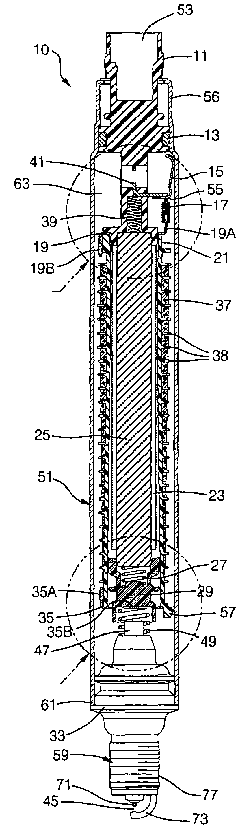
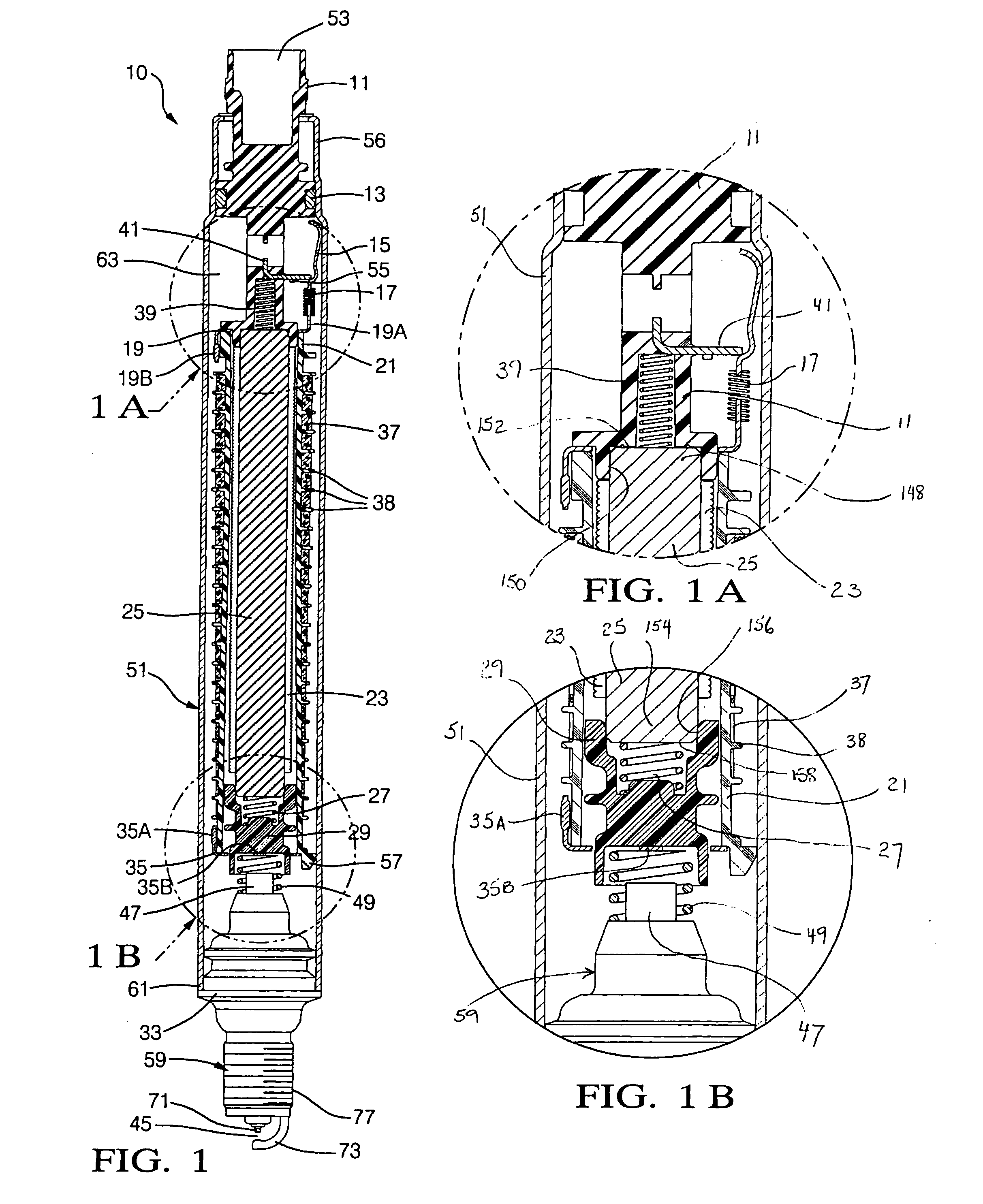
[0026]Referring to the figures, and particularly to FIGS. 1, 1A and 1B, a preferred embodiment of an integrated ignition coil and spark plug assembly in accordance with the present invention is illustrated in partial sectional view and is generally designated by the reference numeral 10. The integrated ignition coil and spark plug assembly 10 is adapted for installation with a conventional internal combustion engine through a spark plug well and in threaded engagement with a spark plug opening into an engine combustion chamber. The assembly 10 has a substantially rigid outer case 51 at one end of which is a spark plug assembly 59 and at the other end of which is a connector body 11 for establishing an external electrical interface. The assembly 10 further comprises a substantially slender high voltage transformer including substantially coaxially arranged primary and secondary windings and a high permeability magnetic core. All high voltage ignition system components are housed with...


PUM

PropertyMeasurementUnit
diameteraaaaaaaaaa
axial lengthaaaaaaaaaa
wrap angleaaaaaaaaaa

Abstract

An ignition coil intended for application in automotive internal combustion engines includes a generally cylindrically magnetic core defining opposed first and second ends and a primary coil concentrically wound externally about the core axially between the opposed ends. A secondary coil assembly including an insulating spool and a secondary coil wound thereon is concentrically disposed externally of the primary coil and magnetic core. One terminal of the primary coil is connected to a controlled voltage source and the other terminal to an electrical ground. One terminal of the secondary coil is connected to the high voltage terminal of at least one spark plug and the other terminal is connected to an electrical ground. The magnetic core is constructed from low carbon steel rope, preferably in a 1x37 format.

Description

RELATED PATENT APPLICATION[0001]This application is related to U.S. application Ser. No. 763,574 filed 10 Dec. 1996, entitled “Integrated Ignition Coil and Spark Plug”, now U.S. Pat. No. 5,706,792 issued 13 Jan. 1998, the specification of which is expressly incorporated herein by reference.TECHNICAL FIELD[0002]The present invention is related to internal combustion engine ignition apparatus and, more particularly, to high voltage ignition source hardware.BACKGROUND OF THE INVENTION[0003]Ignition apparatus for providing a spark to the combustion chamber of an internal combustion engine characterized by a combined spark plug and ignition coil have been proposed in the prior art. For example, U.S. Pat. No. 1,164,113 to Orswell entitled “Sparking Plug”, U.S. Pat. No. 1,302,308 to Cavanagh entitled “Spark Coil for Ignition”, U.S. Pat. No. 2,441,047 to Wall entitled “Transformer Spark Plug”, U.S. Pat. No. 2,459,856 to Wall entitled “Transformer Spark Plug”, U.S. Pat. No. 2,467,531 to Lamp...

Claims


Application Information

Patent Timeline
Patent Type & Authority Applications(United States)
IPC IPC(8): H01F38/12
CPCH01F3/06H01F38/12H01F2038/122H01F41/04H01F41/02
Inventor SKINNER, ALBERT ANTHONYLEVERS, HARRY OLIVERHAMER, COLIN
Owner DELPHI TECH INC
Why Eureka
Try Eureka