
Gas storage container

a technology for gas storage containers and gas tanks, applied in the direction of storage containers preventing decay, liquid transfer devices, drying solid materials, etc., can solve the problems of increased weight of fuel cell vehicles, increased load on fuel cells, inconvenience, etc., and achieves the effect of reducing temperature rise and small siz

Inactive Publication Date: 2008-06-19
HONDA MOTOR CO LTD
View PDF13 Cites 32 Cited by
  • Summary
  • Abstract
  • Description
  • Claims
  • Application Information

AI Technical Summary

Benefits of technology

[0013]A general object of the present invention is to provide a gas storage container, which makes it possible to suppress a temperature rise during filling of the container with a gas, even though the gas storage container is lightweight and small in size.
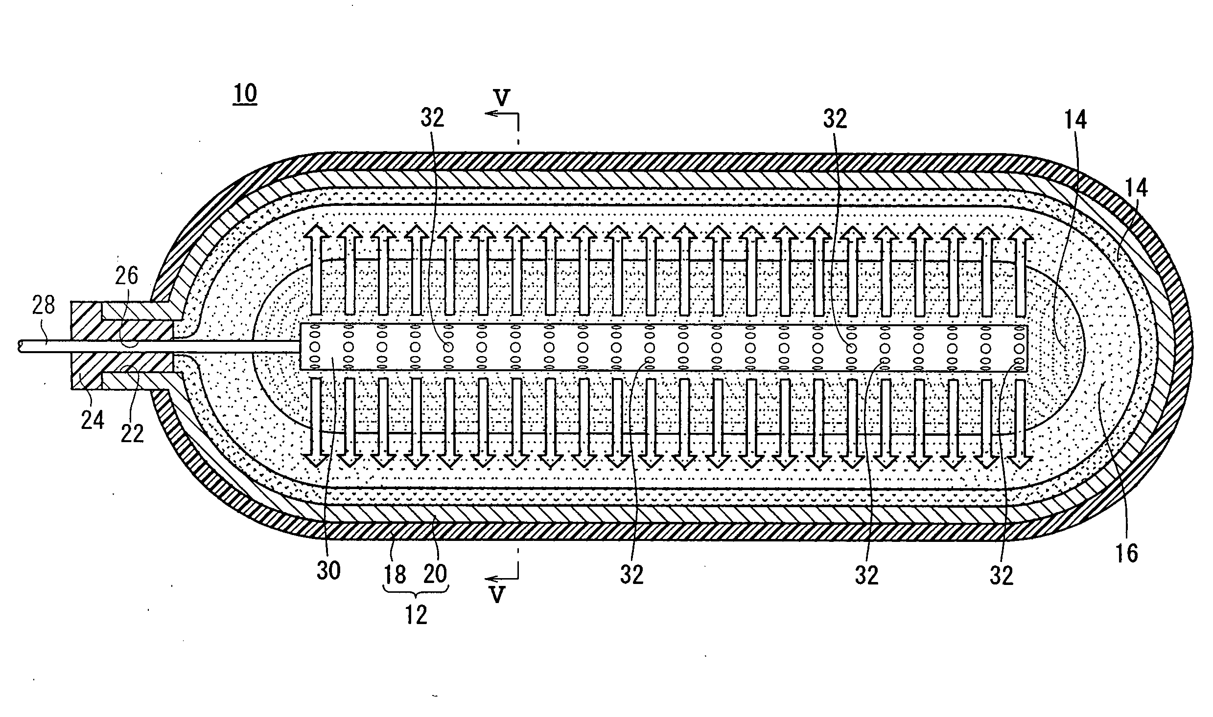
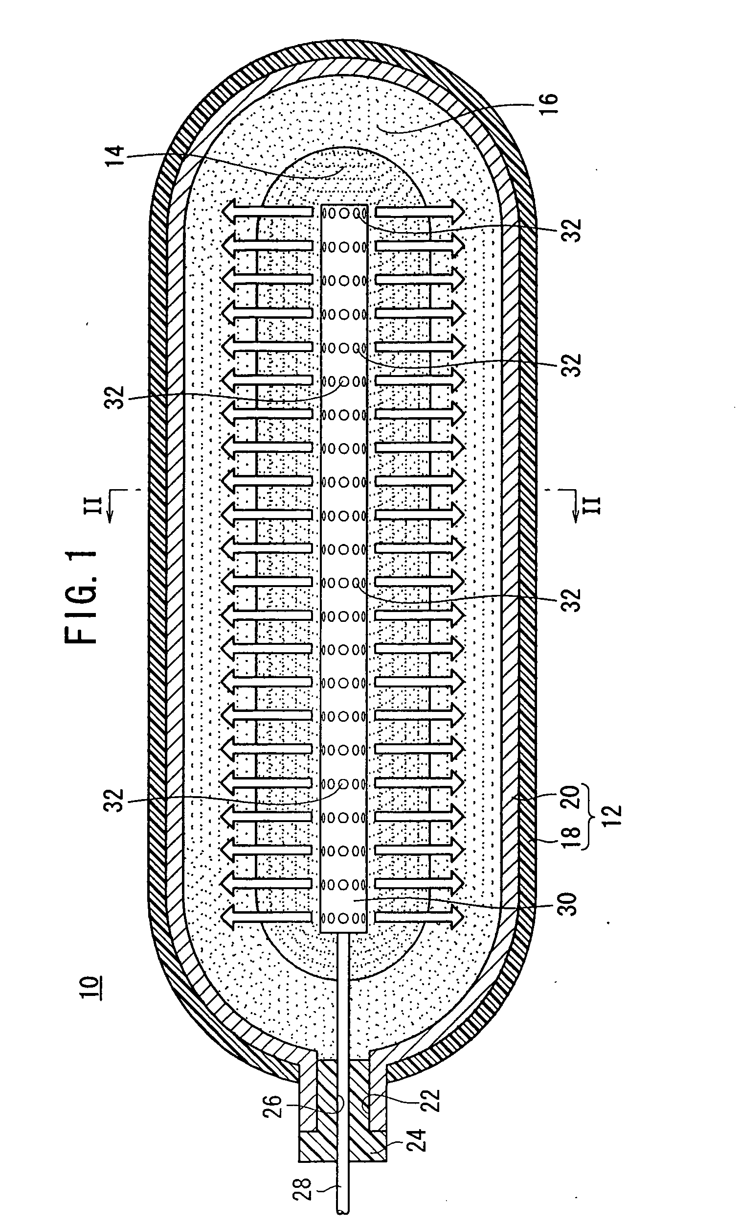
[0019]In the above-described arrangement, the elongate gas distributing tube extends in a longitudinal direction of the container. Therefore, the temperature can be raised substantially equivalently in the longitudinal direction of the container. In other words, the occurrence of an uneven temperature in the longitudinal direction can be avoided.
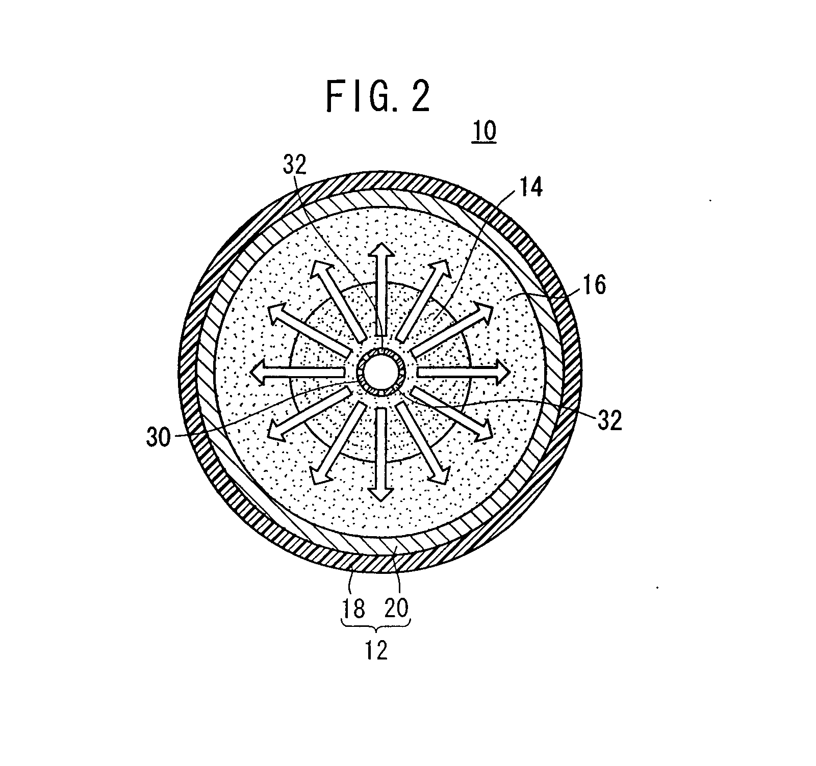
[0020]The gas is discharged while being directed toward the inner side wall of the container. Therefore, the gas absorbing / adsorbing material, which surrounds the gas distributing tube, is cooled by the low temperature gas that is discharged from the gas distributing tube during filling of the container with gas. Therefore, the heat storage material need not be arranged in the vicinity of the gas distributing tube, and hence the used amount of heat storage material can be reduced. The used amount of the gas absorbing / adsorbing material can be relatively increased, and therefore, the gas accommodating amount is increased.
[0021]Further, heat is absorbed by the heat storage material contained in the mixture, in the vicinity of the inner side wall of the container. Therefore, a rise in temperature is suppressed. Accordingly, absorbing and / or adsorption of the gas by the gas absorbing / adsorbing material contained within the mixture is not inhibited. Consequently, in addition, gas is efficiently occluded and / or adsorbed by the gas absorbing / adsorbing material in the vicinity of the inner side wall of the container. Therefore, the gas accommodating amount can be improved without increasing the volume of the container in order to accommodate a large amount of gas absorbing / adsorbing material. As a result, a gas storage container can be constructed, which is lightweight and small in size, and which exhibits a large gas storage density per unit volume or per unit weight.
[0023]It is also preferable that a gas absorbing / adsorbing material further be arranged outside of the mixture. With this arrangement as well, a rise in temperature inside the container is suppressed under action of the heat storage material. Therefore, even when a gas absorbing / adsorbing material is arranged only in the vicinity of the inner side wall of the container, occluding (absorbing) and / or adsorption of the gas, which is performed by the gas absorbing / adsorbing material, is not significantly inhibited. Therefore, an increase in the amount of used gas absorbing / adsorbing material is made possible, and accordingly, the gas accommodating amount of the container can be further increased.

Problems solved by technology

However, if an excessively large gas storage container is carried by the vehicle, the weight of the fuel cell vehicle increases.
Consequently, an inconvenience arises in that the load on the fuel cell also is increased.
Further, when the container is filled with the gas, it is accompanied by adiabatic compression.
Therefore, when the gas storage container is filled with hydrogen gas, if the temperature inside the container increases excessively, the occlusion or adsorption of gas by the gas absorbing / adsorbing material is inhibited.
That is, it is impossible to avoid the occurrence of portions therein, which exhibit high temperatures locally within the container.
In this case, depending on the situation, there is a concern that an outer shell and a liner, which make up parts of the container, may become exfoliated from each other.
On the other hand, when a heat storage material is accommodated therein, there is a concern that heat absorption thereby may still be insufficient, due to the high temperature produced locally inside the container.
However, the heat storage material does not contribute to occlusion and / or adsorption of the gas at all.

Method used


Image

  • Gas storage container
  • Gas storage container
  • Gas storage container

Examples


example 1

[0062]A container composed of an aluminum alloy was manufactured, having the shape as shown in FIG. 1, with an inner radius of 164 mm and an internal volume of 8.2 liters. Further, one end of a cylindrical hollow sintered member, made of stainless steel, was enclosed therein to provide a gas distributing tube. The gas distributing tube was connected to a gas supply tube inserted into a through-hole of a closing member. The gas distributing tube was accommodated inside the container by closing an opening of the container with the closing member. Activated carbon, serving as the gas absorbing / adsorbing material, and a mixture of activated carbon and paraffin microcapsules (heat storage material), were also accommodated together inside the container.

[0063]Specifically, a cylindrical container having a radius of 66 mm, which was manufactured from a gas permeable elastic film member made of polyurethane and having a thickness of 0.2 mm, was arranged so as to surround the gas distributing...


PUM

PropertyMeasurementUnit
temperatureaaaaaaaaaa

Abstract

An elongate gas distributing tube, which extends in a longitudinal direction of a container, is accommodated within the container that constitutes a gas storage container. Discharge ports, through which the gas is discharged, are provided only on a side circumferential wall of the gas distributing tube. Therefore, the discharged gas advances while being directed toward the inner side wall of the container. The gas distributing tube is surrounded by a gas absorbing / adsorbing material. On the other hand, the gas absorbing / adsorbing material is surrounded by a mixture, which is prepared by mixing the gas absorbing / adsorbing material with a heat storage material, such that heat is absorbed by the heat storage material contained therein.

Description

BACKGROUND OF THE INVENTION[0001]1. Field of the Invention[0002]The present invention relates to a gas storage container. In particular, the present invention relates to a gas storage container, which accommodates a gas absorbing / adsorbing material therein.[0003]2. Description of the Related Art[0004]As is well known, a fuel cell generates electric power by supplying a fuel gas such as hydrogen to an anode, while supplying an oxygen-containing gas such as oxygen to a cathode. Therefore, for example, a fuel cell vehicle that accommodates the fuel cell carries a gas storage container thereon, which is filled with hydrogen. The fuel cell vehicle runs by using reaction gases made up of atmospheric air, which serves as the oxygen-containing gas, and hydrogen supplied from the gas storage container.[0005]As clearly appreciated from this fact, the larger the hydrogen-accommodating amount of the gas storage container is, the longer the distance that the fuel cell vehicle can successfully ru...

Claims


Application Information

Patent Timeline
Patent Type & Authority Applications(United States)
IPC IPC(8): B65D85/00B65D81/26B65D81/38B67D5/06B67D7/06
CPCF17C11/005H01M8/04216H01M8/04208Y02E60/50
Inventor SUZUKI, TAKANORISOGAWA, YUSUKEFURUTA, TERUMI
Owner HONDA MOTOR CO LTD
Learn More