Substrate processing apparatus and method

Active Publication Date: 2008-06-19
KLA TENCOR CORP
View PDF9 Cites 27 Cited by
  • Summary
  • Abstract
  • Description
  • Claims
  • Application Information

AI Technical Summary

Benefits of technology

[0094]It may be seen from the preceding discussion that the stage controller 714 and stage 710 provide correction for a low-frequency component of the beam-substrate position error and the beam controller 718 and beam deflection 720 provide correction for a high-frequency component of the beam-substrate position error. The stage controller 714 and beam controller 718 may receive additional input from adaptive Filter Logic 728 which may be implemented in hardware or in software, e.g., in the form of adaptive control algorithms. By way of example, the adaptive filter logic 728 may use Kalman filtering. The adaptive filter logic 728 may receive input from the Stage Metrology System 704. There are a number of different possible implementations of the adaptive filter logic 728. For example an imbalance between actuators used to translate the rotary stage in the x direction may cause a variation in the angular speed of the rotary stage. The sensors used in the stage metrolo

Problems solved by technology

However, the factor limiting the throughput is the mechanical motion of the Cartesian stage.
As the data path electronics get faster, this mechanical limitation of Cartesian systems becomes more limiting, and the data path rendering in polar coordinates becomes easier.
The data path rendering speed is expected to continue to follow the Moore's law and improve w

Method used


Image

  • Substrate processing apparatus and method
  • Substrate processing apparatus and method
  • Substrate processing apparatus and method

Examples


Embodiment Construction

[0030]Although the following detailed description contains many specific details for the purposes of illustration, anyone of ordinary skill in the art will appreciate that many variations and alterations to the following details are within the scope of the invention. Accordingly, the exemplary embodiments of the invention described below are set forth without any loss of generality to, and without imposing limitations upon, the claimed invention.

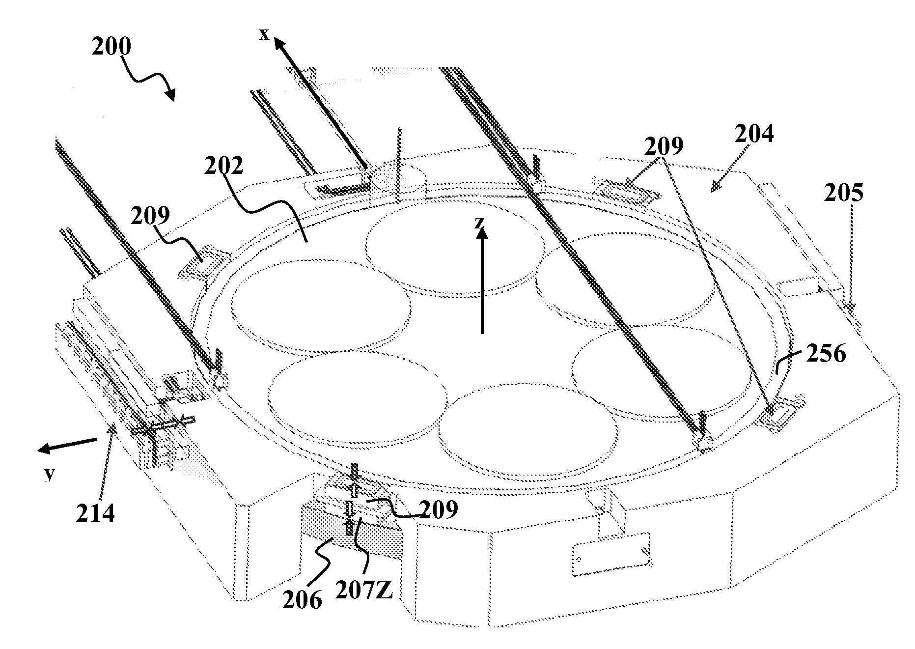
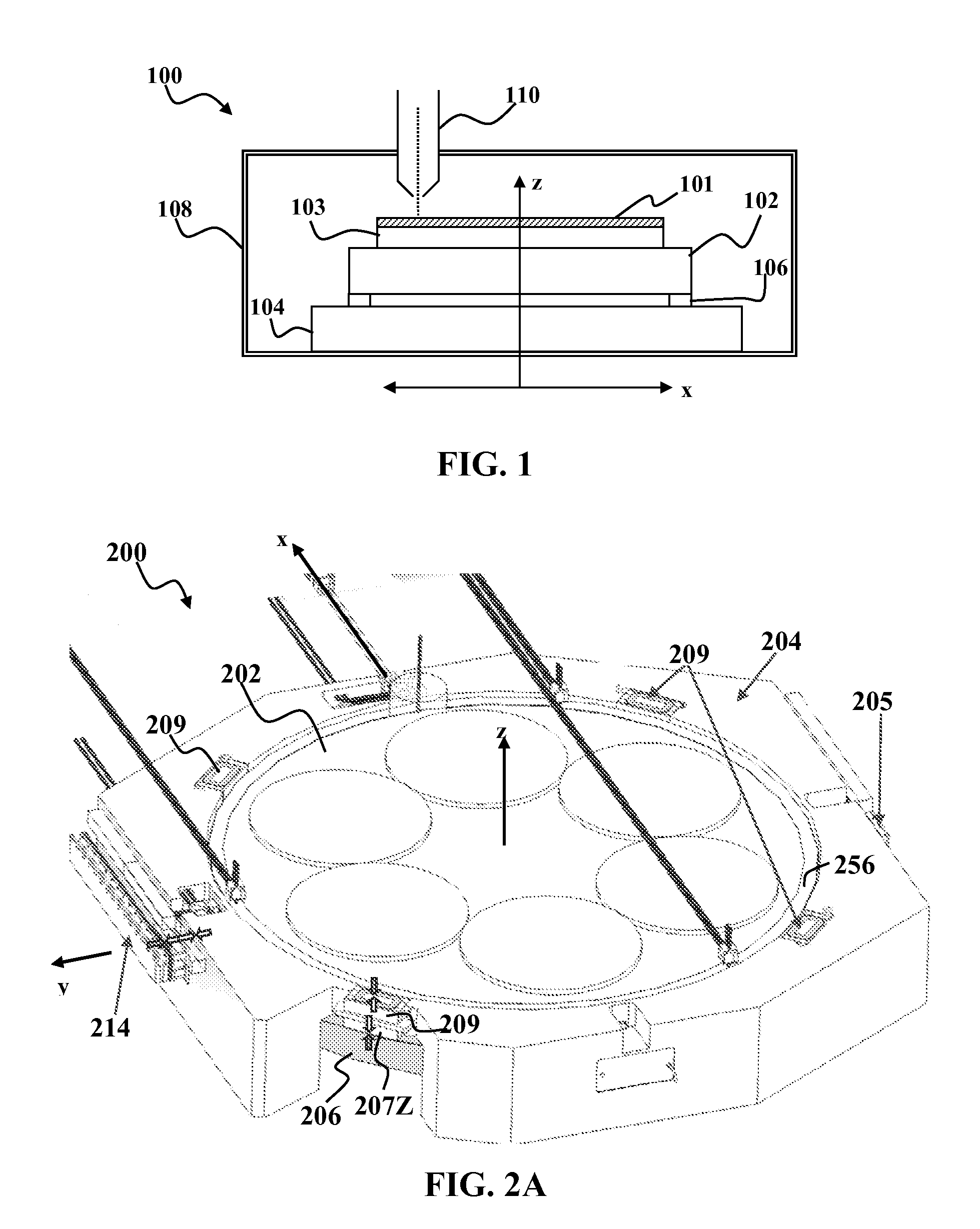
[0031]An example of a substrate processing apparatus 100 according to an embodiment of the present invention is depicted schematically in FIG. 1. The apparatus 100 generally includes a first stage 102 and a second stage 104. The first stage 102 carries one or more substrate chucks 103. Each substrate chuck 103 is adapted to support and retain a substrate 101. Examples of suitable substrates include, but are not limited to, semiconductor wafers, or reticles for optical lithography. The first stage 102 moves with respect to the second stage 10...


PUM


Abstract

A substrate processing apparatus and method are disclosed.

Description

CROSS-REFERENCE TO A RELATED APPLICATION[0001]This application claims priority from co-pending provisional patent application Ser. No. 60 / 870,528, which was filed on Dec. 18, 2006, the entire disclosures of which are incorporated herein by reference.GOVERNMENT INTERESTS[0002]This invention was made with Government support under Agreement HR0011-06-3-0008 awarded by the Defense Advanced Research Projects Agency (DARPA). The Government has certain rights in the invention.FIELD OF THE INVENTION[0003]This invention generally relates to substrate inspection and lithography and more particularly to movable stages used in substrate inspection and lithography.BACKGROUND OF THE INVENTION[0004]Historically wafer writing in lithography and scanning in metrology and inspection systems have used linear stepping or scanning motion to translate a substrate. Rectilinear motion has the advantages of simplicity in the rendering process, since the die on a semiconductor wafer are typically arranged in...

Claims


Application Information

Patent Timeline
IPC IPC(8): H01J37/20
CPCH01J37/20H01J2237/201H01J2237/202H01J2237/26H01L21/68771H01L21/6719H01L21/68H01L21/68764H01J2237/317
Inventor ZYWNO, MAREKBAREKET, NOAH
Owner KLA TENCOR CORP
Why Eureka
Try Eureka