Conversely, a serial connection may fail to provide the required current, so that several strings of serial connections may need to be connected in parallel to provide the required current.
For example, various inconsistencies in manufacturing may cause two identical sources to provide different output characteristics.
The problem facing the solar array designer is to produce a standard
AC current at 120V or 220V root-mean-square (RMS) from a combination of the low voltages of the solar panels.
The delivery of high power from a
low voltage requires very high currents, which cause large conduction losses on the order of the second power of the current (I2).
While this configuration is advantageous in terms of cost and architecture simplicity, several drawbacks have been identified in the literature for such architecture.
One recognized drawback is inefficiencies cause by non-optimal power draw from each individual panel, as explained below.
Consequently, the arrangement is not operated at best achievable efficiency.
Forcing a single current through all of the panels of the string causes the individual panels to work at a non-optimal power point and can also cause panels which are highly mismatched to generate “hot spots” due to the
high current flowing through them.
Due to these and other drawbacks of conventional centralized methods, the solar panels have to be matched properly.
In conventional multiple string configurations all strings have to be composed of exactly the same number of solar panels and the panels are selected of the same model and must be install at exactly the same spatial orientation, being exposed to the same
sunlight conditions at all times. This is difficult to achieve and can be very costly.
As noted in some of the above cited works, integrating inverters into the individual cells has many drawbacks, including high costs, low safety (especially in solar installations), and reliability.
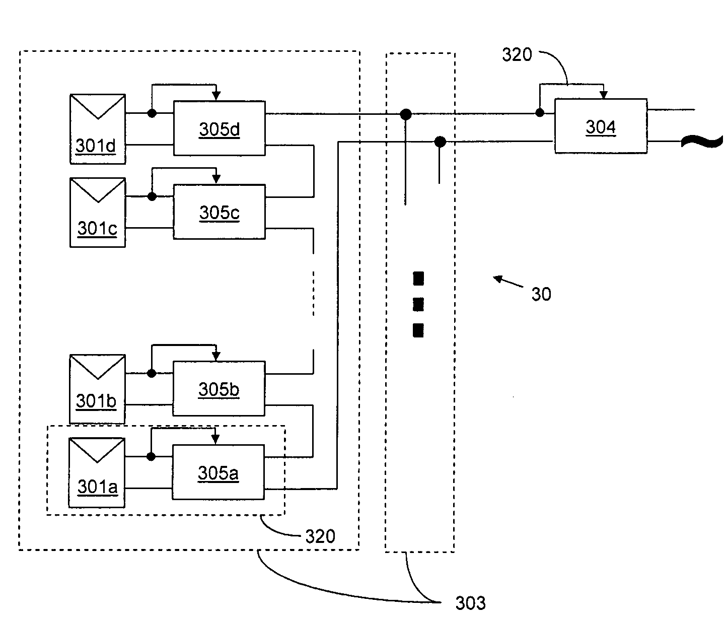
However, incorporating MPPT into each panel is still problematic in serial application, as each MPPT would attempt to drive its source at different current, while in a serial connection the same current must flow through all of the panels.
Moreover, it is unclear what type of DC-
DC converter would provide the best results and how to incorporate an MPPT into such an arrangement.
As already mentioned above, various environmental and operational conditions
impact the
power output of DC power sources.
Owners and even professional installers find it difficult to verify the correct operation of the
solar system.
With time, many other factors, such as aging, dust and
dirt collection and module degradation affect the performance of the solar array.
Since these cells are expensive, they are usually used in CPV applications which call for smaller cells.
However, the
power output of CPV installations now depends upon fluctuations in the intensity of different parts of the spectrum of the sun (and not only the total intensity), and imperfections or distortions in the lenses or mirrors used.
Another field in which traditional photovoltaic installations face many problems is the developing market of building-integrated
photovoltaics (BIPV).
Thus, BIPV installations suffer greatly from local partial shading due to the existence of other structural elements in the vicinity of the panels.
Since in traditional solutions the panels are stringed together to a joint MPPT, much power is lost.
Yet another problem with traditional installations is the poor energy utilization in cases of low sun-light.
If there is low light, the aggregated voltage from the panels may not reach this minimal value, and the power is thus lost.
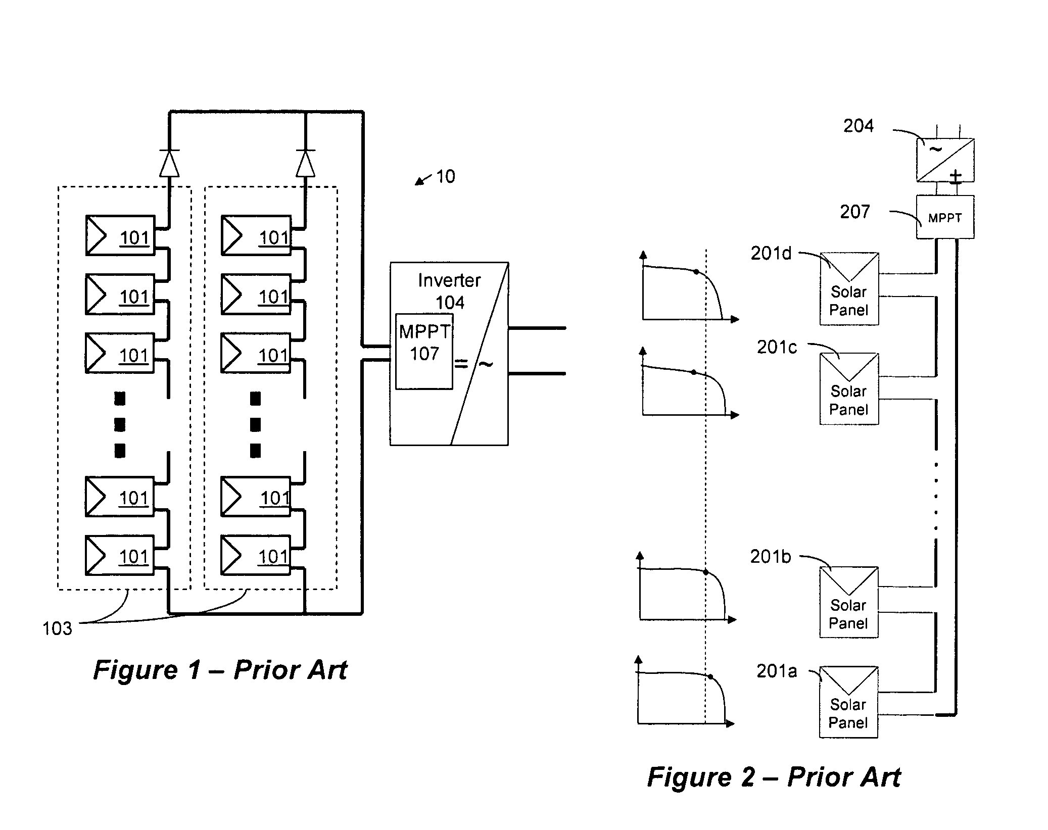
In practice, however, individual panels and strings are generally either not tested at all or tested only prior to connection.
This happens because current measurement is done by either a series connection to the solar array or a series
resistor in the array which is typically not convenient.
Therefore, the performance information provided by monitoring at the inverter 104 is usually not sufficient to understand if
power loss is due to environmental conditions, from malfunctions or from poor installation or maintenance of the solar array.
Furthermore, integrated information does not pinpoint which of solar panels 101 is responsible for a detected
power loss.

