Method and apparatus for acoustic sensing using multiple optical pulses

a technology of optical pulses and acoustic sensing, applied in the field of sensing signals, can solve problems such as failures, lack of redundancy within these networks, and significant cost to the network operator in both customer dissatisfaction and loss of revenue,

Active Publication Date: 2008-06-19
AMERICAN TELEPHONE & TELEGRAPH CO
View PDF4 Cites 45 Cited by
  • Summary
  • Abstract
  • Description
  • Claims
  • Application Information

AI Technical Summary

Benefits of technology

[0013]The present invention involves an improved electromagnetic-wave, time-domain-reflectometry technique that may be used, in one specific embodiment, to detect acoustic waves in the vicinity of buried optical fibers. In a specific application of the invention, such acoustic waves may foretell impending damage to the buried optical fiber, such as by improper excavation. The technique, in one embodiment, involves launching into a medium, a plurality of groups of pulse-modulated electromagnetic-waves. The frequency separation between the electromagnetic waves in two pulses within a first group is different from the frequency separation between the electromagnetic waves in two pulses within a second group. A beat signal between the pulses of light that are scattered by the medium is then detected, and, in one embodiment, that signal may be used to determine a characteristic of the environment in which the medium is located. For example, if the medium is a buried optical fiber into which optical pulses have been launched in accordance with the invention, the presence of acoustic waves within the region of the buried fiber can be detected.

Problems solved by technology

With more recent demands for increased bandwidth for data and Internet traffic, the lack of redundancy within these networks has become a cause for concern.
If a link within a network fails, there may be a significant cost to the network operator in both customer dissatisfaction and lost revenue.
Such failures may occur, for example, when excavations associated with construction sever an optical fiber cable.
However, unforeseen network failures still occur due to physical damage to the fiber plant.
A security sensor of this nature would be unobtrusive and, if buried around the perimeter of a sensitive facility, would be virtually impossible to locate and disable.
However, determining the location of the disturbance, and isolating a section of fiber from a persistent, non-threatening, disturbance, proves difficult due to the nature of these devices.
Limited success has however been achieved using loop architectures, but due to the reciprocal nature of the loop configuration multiple disturbances of an unknown nature prove virtually impossible to separate and locate independently.
This problem extends to any forward-propagating differential time-delay method.
Although these techniques seem useful, there are several limitations in the disclosed systems.
The most crucial limitation is reliability in detecting a threat, since missed detection would cause concern in many applications.
Another concern is that the signal returned from such a sensor is extremely non-linear and it may be difficult to identify an acoustic disturbance since the acoustic signature is distorted by the generation of harmonics associated with this non-linear response.

Method used


Image

  • Method and apparatus for acoustic sensing using multiple optical pulses
  • Method and apparatus for acoustic sensing using multiple optical pulses
  • Method and apparatus for acoustic sensing using multiple optical pulses

Examples


Embodiment Construction

[0020]Overview

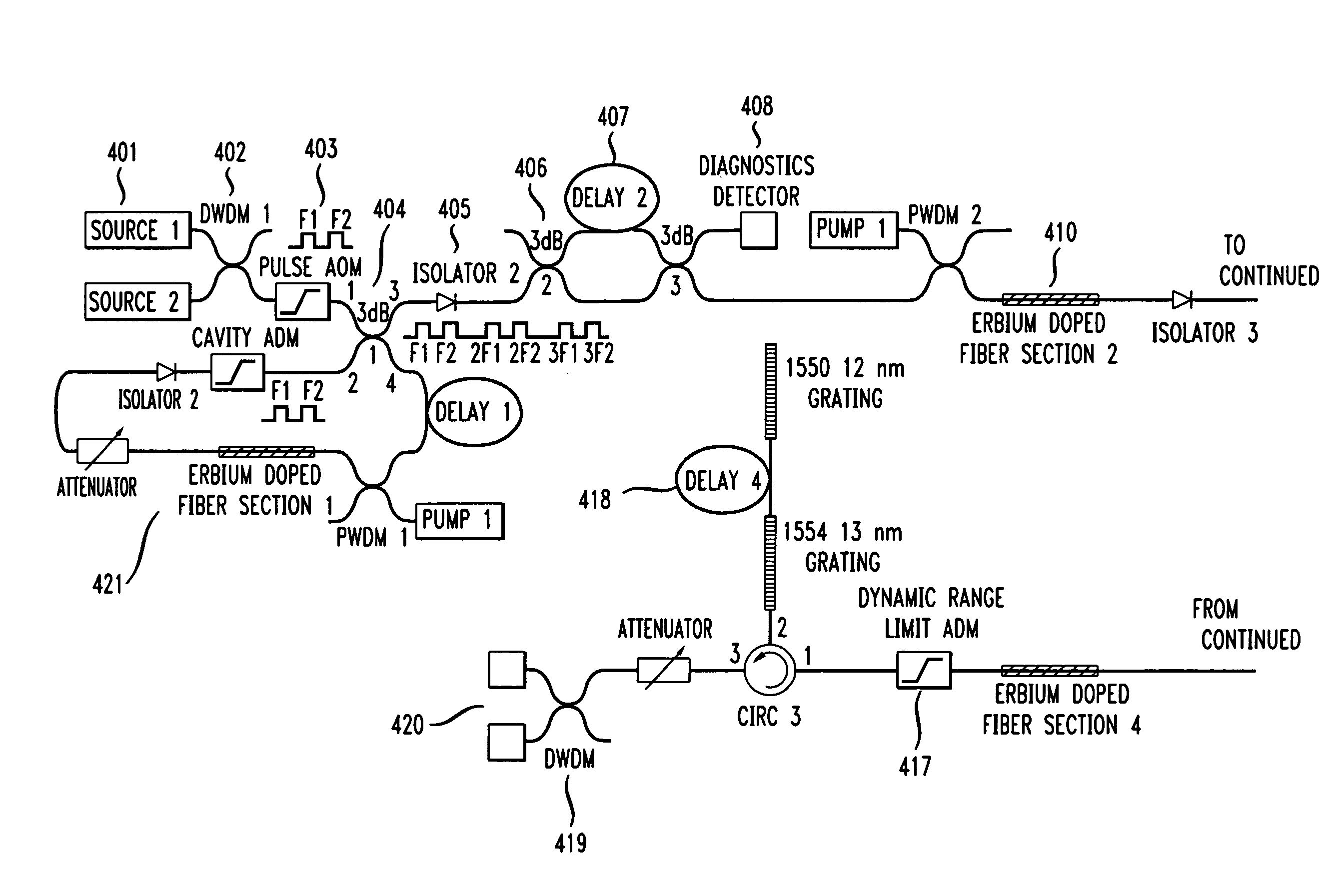
[0021]The present invention involves an improved optical time-domain-reflectometry technique that may be used to detect acoustic waves in the vicinity of buried optical fibers. The invention will first be described first at a high level in terms of a specific embodiment. Thereafter the invention will be described with greater specificity.

[0022]The inventive technique, in one embodiment, involves launching optical pulses into a buried optical fiber and detecting the signal backscattered by the fiber. The optical frequency of one pulse within a pair of pulses differs slightly from the optical frequency of the other pulse within the pair of pulses. This frequency difference (or separation) itself varies from one pair of pulses to the next. This variation in frequency difference results in a detected backscattered signal having a phase that is modulated by an acoustic signal in the vicinity of the fiber, allowing decoding of the disturbance with improved signal to noise ra...


PUM

PropertyMeasurementUnit
frequencyaaaaaaaaaa
frequencyaaaaaaaaaa
frequencyaaaaaaaaaa

Abstract

An improved technique for acoustic sensing involves, in one embodiment, launching into a medium, a plurality of groups of pulse-modulated electromagnetic-waves. The frequency of electromagnetic waves in a pulse within a group differs from the frequency of the electromagnetic waves in another pulse within the group. The energy scattered by the medium is detected and, in one embodiment, the beat signal may be used to determine a characteristic of the environment of the medium. For example, if the medium is a buried optical fiber into which light pulses have been launched in accordance with the invention, the presence of acoustic waves within the region of the buried fiber can be detected

Description

BACKGROUND OF THE INVENTION[0001]The present invention relates generally to sensing signals using multiple pulses of electromagnetic radiation. In a specific embodiment, the invention relates more particularly to acoustic sensing using multiple optical pulses.[0002]The telecommunications industry now uses optical fiber optic cables to form the vast majority of its network backbone. With advances in technology, a single cable bundle can carry many thousands or even millions of telephone conversations. With more recent demands for increased bandwidth for data and Internet traffic, the lack of redundancy within these networks has become a cause for concern. If a link within a network fails, there may be a significant cost to the network operator in both customer dissatisfaction and lost revenue. Such failures may occur, for example, when excavations associated with construction sever an optical fiber cable. Accordingly, the protection of these buried resources is a high priority for ne...

Claims


Application Information

Patent Timeline
Patent Type & Authority Applications(United States)
IPC IPC(8): G01N21/00G01B9/02H04B10/071
CPCG01M11/3127H04B10/071G01M11/3172G01D5/35364G01H9/004G08B13/1654G08B13/169
Inventor LEWIS, ANDREW B.RUSSELL, STUART
Owner AMERICAN TELEPHONE & TELEGRAPH CO
Why Eureka
Try Eureka