
Method for detecting abnormality of temperature sensor in machine tool

a technology of temperature sensor and machine tool, which is applied in the direction of instruments, heat measurement, calorimeters, etc., can solve the problems of abnormal temperature sensor abnormality detection, increased machining dimensional error, and inability to perform normal correction, so as to prevent abnormal correction amount during machining, reduce cost, and easy to identify

Inactive Publication Date: 2008-06-19
OKUMA CORP
View PDF3 Cites 25 Cited by
  • Summary
  • Abstract
  • Description
  • Claims
  • Application Information

AI Technical Summary

Benefits of technology

[0007]In the above mentioned conventional case, when an abnormal temperature is detected due to disconnection or short circuit in the temperature sensor, or failure of the temperature measuring device is detected, a normal correction may not be performed and the machining dimensional error may increase. Further, the moving body of the machine may collide with a workpiece due to an abnormal correction amount, so that the abnormality of the temperature sensor needs to be detected. The abnormality of the temperature sensor, such as disconnection or short circuit, can be easily detected by monitoring the temperature information from each of the temperature sensors. On the other hand, for example, the abnormality or the like due to aged deterioration of the thermistor cannot be detected solely by the temperature sensor or temperature measuring device. Therefore, there has been employed a method in which, for example, a plurality of temperature sensors are arranged at the same place, and the abnormality is detected by comparing a plurality of pieces of temperature information with one another. For this reason, the number of temperature sensors or temperature measuring devices increases, resulting in an increase in cost.
[0012]A fourth aspect of the present invention is, in addition to the object of any of the first aspect 1 to the third aspect 3, configured to include the step of: prohibiting any changes of correction amount in thermal displacement correction of the machine tool when a certain temperature sensor is determined abnormal. With this configuration, a failure due to an abnormal correction amount during machining is prevented.
[0013]According to the present invention, a detection of abnormality of the detected temperature is simply performed without extra time. As a result, it is not necessary to increase the number of temperature sensors or temperature measuring devices for detecting the abnormality, resulting in reduction of the cost.
[0015]According to the third aspect of the present invention, in addition to the effects of the first aspect or the second aspect, the temperature sensors can be easily identified without reviewing detected temperatures of respective parts, as the temperature sensors are grouped based on the different attachment areas that are distinguishable based on whether the areas are affected by the heat sources and the height from a floor surface.

Problems solved by technology

In the above mentioned conventional case, when an abnormal temperature is detected due to disconnection or short circuit in the temperature sensor, or failure of the temperature measuring device is detected, a normal correction may not be performed and the machining dimensional error may increase.
Further, the moving body of the machine may collide with a workpiece due to an abnormal correction amount, so that the abnormality of the temperature sensor needs to be detected.
On the other hand, for example, the abnormality or the like due to aged deterioration of the thermistor cannot be detected solely by the temperature sensor or temperature measuring device.
For this reason, the number of temperature sensors or temperature measuring devices increases, resulting in an increase in cost.

Method used


Image

  • Method for detecting abnormality of temperature sensor in machine tool
  • Method for detecting abnormality of temperature sensor in machine tool
  • Method for detecting abnormality of temperature sensor in machine tool

Examples


Embodiment Construction

[0024]An embodiment of the present invention will hereinafter be described based on the drawings.

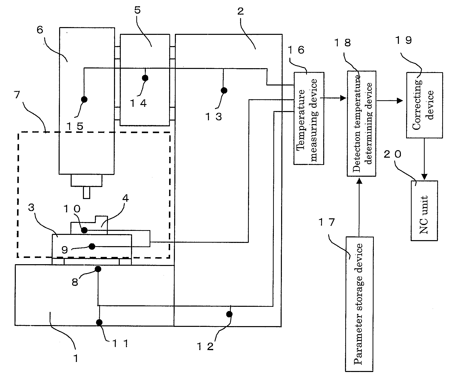
[0025]FIG. 1 is a schematic diagram of a vertical machining center as one example of a machine tool as viewed from its side. On a right-hand side of a bed 1, a column 2 is securely installed. Further on a rail provided on an upper surface of the bed 1, a table 3 is placed movably in a horizontal (right-and left) direction of the diagram and a work 4 can be fixed on an upper surface of the table 3. On a rail provided on a left-hand side surface of the column 2, a saddle 5 is constructed movably in a direction perpendicular to the drawing, and on a left-hand side surface of the saddle 5, a main spindle head 6 is constructed movably in a vertical (up-and down) direction of the drawing.

[0026]Further, a dashed line 7 represents a machining space enclosed by a cover. In the machining space 7, cutting fluid is discharged from an unshown nozzle provided on a main spindle at the bottom of the mai...


PUM

PropertyMeasurementUnit
temperaturesaaaaaaaaaa
areaaaaaaaaaaa
heightaaaaaaaaaa

Abstract

The invention relates to a method for detecting an abnormality of a temperature sensor.A plurality of temperature sensors are preliminarily grouped for each of predetermined attachment areas of a machine tool, and after a temperature of each part is measured in S1, the detected temperatures are classified in S2 for each of the grouped attachment areas, and then sorted in descending order in S3. Subsequently, a difference ΔT between any closest two of the detected temperatures is obtained in S4, and then compared with a preset limit value γ in S5, when ΔT exceeds the limit value γ, temperature sensors in a corresponding attachment area are determined abnormal in S6, and an alarm is displayed.

Description

[0001]This application claims the benefit of Japanese Patent Application Number 2006-340429 filed on Dec. 18, 2006 the entirety of which is incorporated by reference.FIELD OF THE INVENTION[0002]The present invention relates to a method for detecting an abnormality of a temperature sensor used for correcting thermal displacement of a machine tool.DESCRIPTION OF THE BACKGROUND ART[0003]In a machine tool, a thermal displacement correcting method for correcting a machining dimensional error caused by surrounding room temperature variation or cutting heat is often used. The method is configured such that a temperature sensor such as a thermocouple or thermistor is provided on each of components of the machine tool, temperature information from the temperature sensor is obtained by means of use of a temperature measuring device such as a voltmeter or ammeter, a thermal displacement amount is estimated from the obtained temperature information to calculate a correction amount for a moving ...

Claims


Application Information

Patent Timeline
Patent Type & Authority Applications(United States)
IPC IPC(8): G01K15/00
CPCG01K15/007G01K15/00
Inventor SATO, REIJI
Owner OKUMA CORP
Learn More