High-capacity toner cartridge and toner agitator

a toner agitator and high-capacity technology, applied in the field of toner cartridges, can solve the problems of physical limitations, print engine operation may suddenly cease, and enforce limitations, and achieve the effects of lowering load, facilitating operation, and increasing efficiency

Inactive Publication Date: 2008-06-19
TURBON AMERICA
View PDF6 Cites 8 Cited by
  • Summary
  • Abstract
  • Description
  • Claims
  • Application Information

AI Technical Summary

Benefits of technology

[0011]This invention overcomes the disadvantages of the prior art by providing an agitator blade and toner cartridge employing such an agitator blade that enables a higher capacity of toner while lowering the load exerted by the print engine motor as toner is agitated. This blade and cartridge also allows for greater efficiency at low toner levels as the blade is brought closer to the inner wall of the cartridge toner tank. The blade consists of an axially directed axle shaft having a plurality of rigid, radially directed ribs that extend to a location proximate to the inner wall of the tank. A plurality of cross bar members are mounted between each pair of ribs. The cross bar members are constructed from a relatively thin, flexible polymer sheet and include a pair of radially directed side walls that extend to an L-shaped cross bar. The side walls lay relatively flushly against adjacent walls of ribs. The side walls are mounted in a manner that is not rotationally fixed, so as to freely rotate on the axle shaft. Each L-shaped cross bar includes axially extended, rib-engaging wings that seat within recesses in each rib. The wings and recesses re mounted SO that the cross bars are generally prevented from passing between the ribs when the cross bars are driven by the ribs in the normal direction of agitator rotation. However, the wings are sufficiently resilient so that a predetermined level of toner resistance, typically at high fill levels, causes the wings and cross bars to elastically deform and pass through the ribs, leaving only the thinner ribs to traverse the toner in that cycle. At the end of the cycle, the agitator ribs meet up with, and engage the cross bar members again, and depending upon the level of toner resistance, the cross bars either (a) hold, passing with the ribs through the toner, or (b) break away for another cycle, until the toner level is sufficiently low. Also, the cross bars are located in closer proximity to the tank inner wall than a conventional agitator, which allows for more efficient scraping and scooping. A second rib-engaging wing can be located along the length of each side wall between the cross bar and base for added support against break-away.
[0012]In an illustrative embodiment, the toner cartridge can include a volume extension member that is sized to fit within the empty space of a corresponding print engine. The cartridge can include a floating timing wheel with at least two different spring tensions for differing levels of toner resistance and the cartridge can include an improved doctor blade that curves along its length to more evenly deposit toner on the image transfer drum. The toner cartridge can also include a compound-angle doctor blade in engagement with the cartridge's developer roller for better distribution of toner.

Problems solved by technology

Some limitations are enforced by electronics within the cartridge and print engine that are set by the manufacturer.
The resulting signal must fall within certain parameters, or a variety of error conditions are indicated by the printer, and print engine operation may suddenly cease.
However, increasing the quantity of toner may also lead to certain physical limitations on performance.
Unfortunately, the higher the level, the greater the drag on the agitator, and hence, the print engine motor.
This reduces its ability to scrape out and scoop up the last bits of toner when the cartridge is nearly empty.

Method used


Image

  • High-capacity toner cartridge and toner agitator
  • High-capacity toner cartridge and toner agitator
  • High-capacity toner cartridge and toner agitator

Examples


Embodiment Construction

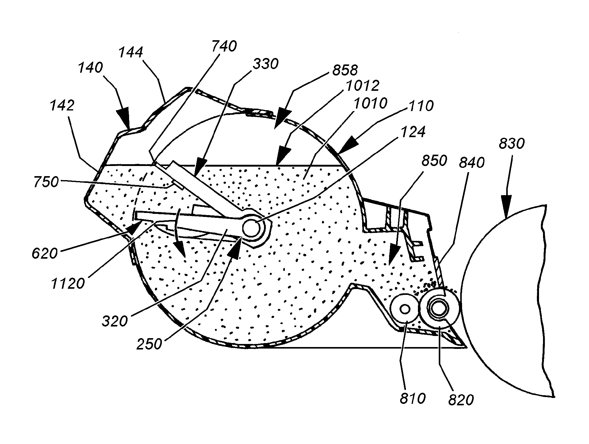
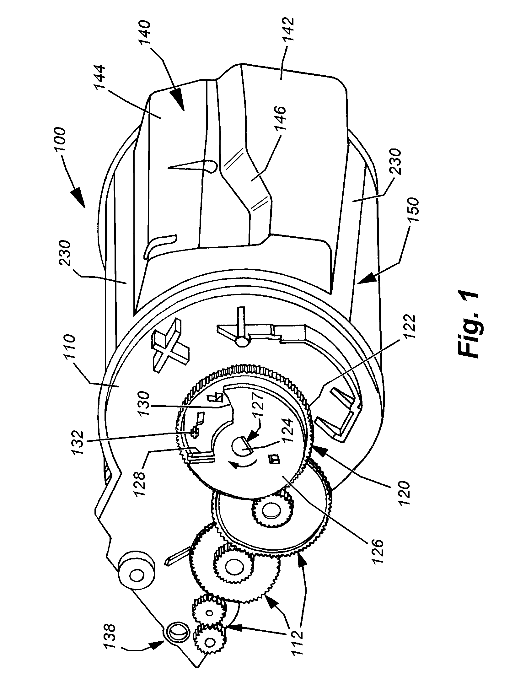
[0026]FIG. 1 details an exemplary toner cartridge 100 for use in accordance with an illustrative embodiment of this invention. This cartridge is employed in, for example, a commercially available T630 print engine, available for Lexmark International, Inc. However, the principles described herein are applicable to a wide variety of other cartridges, available for use in Lexmark and other manufacturers' print engines, including, but not limited to the T620, T630, T640, T520, T530, OptraS, OptraT, and their variations. In general, the teachings herein are applicable to any cartridge that employs an agitator and can deliver toner to the metering area without substantial agitation when filled to a high level.

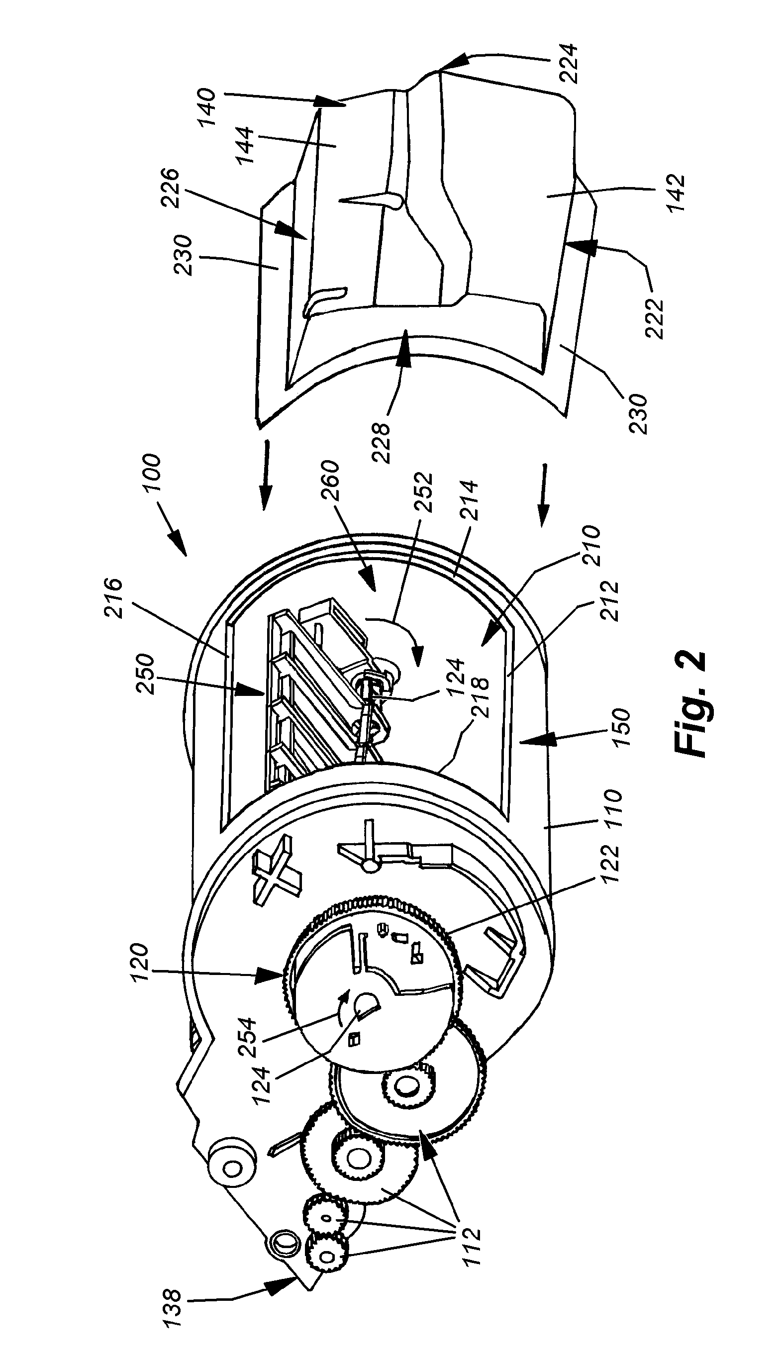
[0027]The exemplary cartridge 100 includes a housing 110 that supports an external gear train 112. At least one of the gears removably engages a print engine drive motor gear (not shown) when the cartridge is properly installed in the print engine. The main agitator gear assembly 12...


PUM


Abstract

This invention provides an agitator blade and toner cartridge employing such an agitator blade that enables a higher capacity of toner while lowering the load exerted by the print engine motor as toner is agitated. This blade and cartridge also allows for greater efficiency at low toner levels as the blade is brought closer to the inner wall of the cartridge toner tank. The blade consists of an axially directed axle shaft having a plurality of rigid, radially directed ribs that extend to a location proximate to the inner wall of the tank. A plurality of cross bar members are mounted between each pair of ribs. Each cross bar includes axially extended, rib-engaging wings. The wings are mounted so that the cross bars are generally prevented from passing between the ribs when the cross bars are driven by the ribs in the normal direction of agitator rotation. However, the wings are sufficiently resilient so that a predetermined level of toner resistance at high fill levels causes the wings and cross bars to elastically deform and pass through the ribs, leaving only the thinner ribs to traverse the toner in that cycle. The toner cartridge can include a volume extension member that is sized to fit within the empty space of a corresponding print engine. The cartridge can also include a compound angle doctor blade for better toner distribution.

Description

BACKGROUND OF THE INVENTION[0001]1. Field of the Invention[0002]This invention relates to toner cartridges used in electronic or laser printers and more particularly to moving agitators for delivering toner from the cartridge's toner tank to its toner metering and delivery components.[0003]2. Background Information[0004]Electronic or “laser” printers use a focused light beam to expose discrete portions of an image transfer drum so that these portions attract printing toner. Toner is a mixture of pigment (typically carbon black or a non-black color component) and plastic. The toner becomes electrostatically attracted to exposed portions of the image transfer drum. As a transfer medium such as paper is passed over the rotating image transferred drum, some of the toner is laid onto the medium. Subsequently, the medium passes through a heated fuser so that the plastic is melted into permanent engagement with the underlying medium.[0005]The vast majority of desktop laser printers current...

Claims


Application Information

Patent Timeline
Patent Type & Authority Applications(United States)
IPC IPC(8): G03G15/08
CPCG03G2215/0844G03G15/0822
Inventor BESSETTE, LIONEL C.
Owner TURBON AMERICA
Why Eureka
Try Eureka