Self-activated warming device

Inactive Publication Date: 2008-06-19
KIMBERLY-CLARK WORLDWIDE INC
View PDF22 Cites 23 Cited by
  • Summary
  • Abstract
  • Description
  • Claims
  • Application Information

AI Technical Summary

Benefits of technology

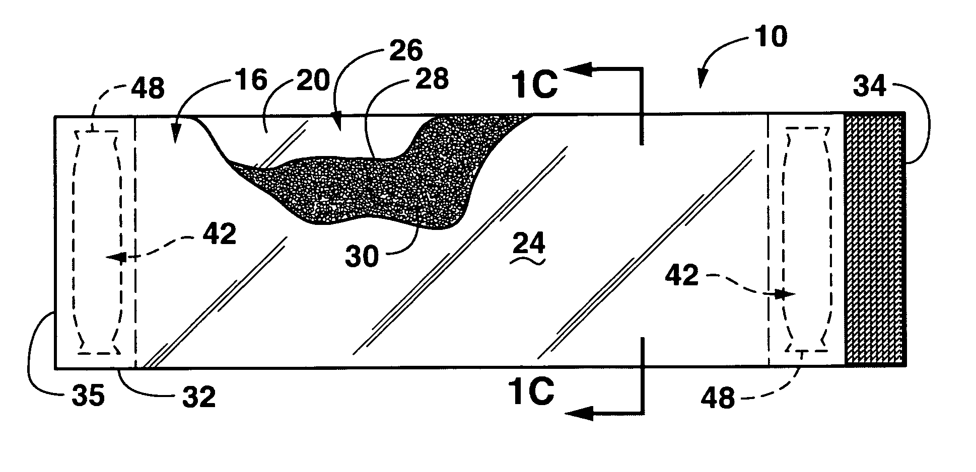
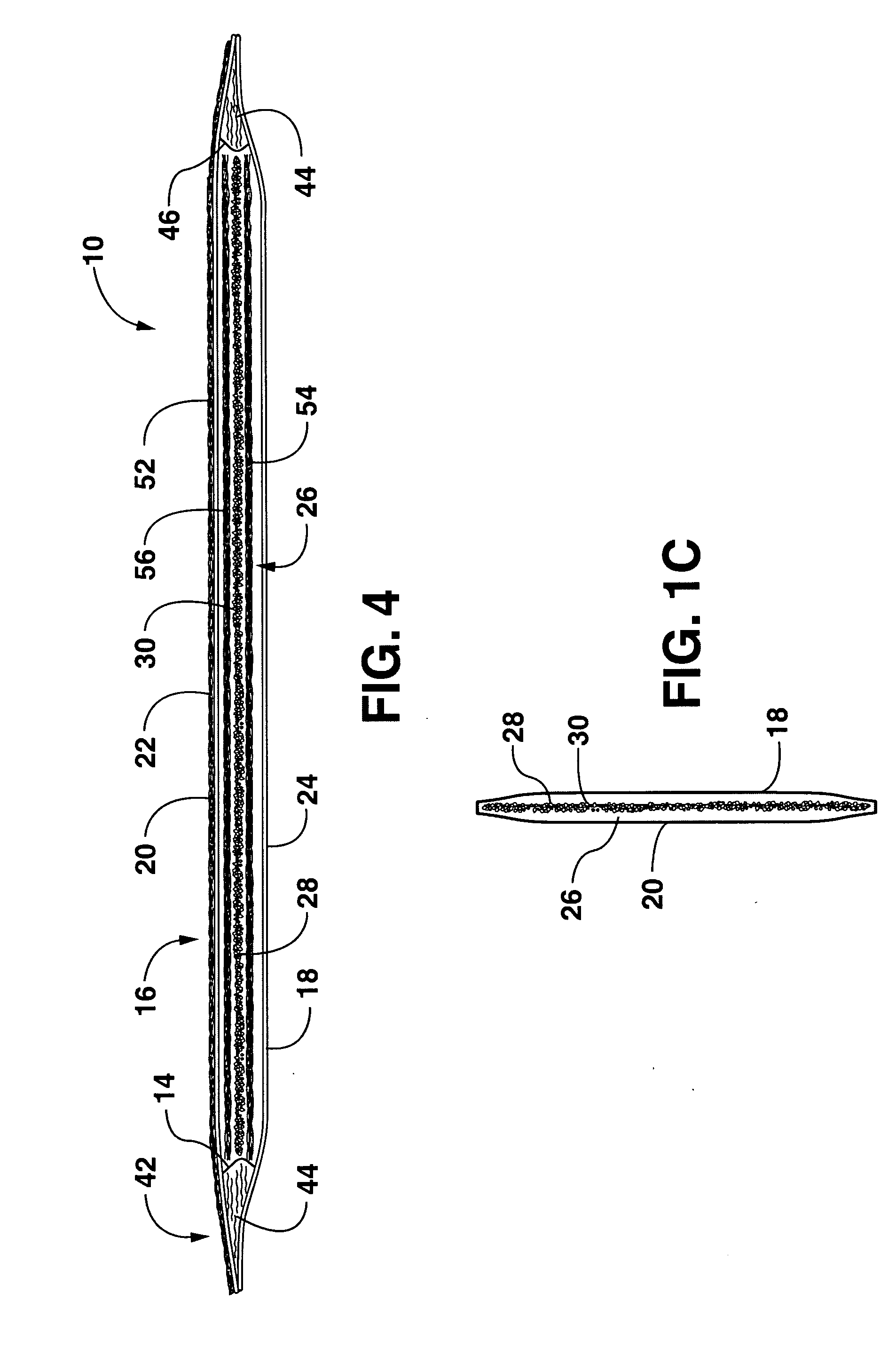
[0017]The liquid source within the interior space of the shell may take on various configurations. For instance, the source may be defined by a liquid-filled compartment defined within the shell, the compartment having a barrier wall or seal that is breached or opened by simple manual manipulation of the device. This compartment may be defined by one or more of the interior surfaces of the shell member. For example, a frangible wall may be attached at the longitudinal ends of the shell member between the opposite interior surfaces of the shell member, with this wall rupturing or breaking upon pressure being applied to the device. In another embodiment, the compartment may be defined entirely by the interior surfaces of the shell member, with a frangible seal between the surfaces separati

Problems solved by technology

Unfortunately, various problems arise when attempting to apply exothermic compositions to a substrate.
Specifically, if the exothermic composition were exposed to moisture during application or storage, the exothermic reaction could occur prematurely.
Certain salts are susceptible to absorbing moisture from the air and may slowly warm over time until an equilibrium moisture rate is reached.
This ultimately would lower the quality of the exothermic composition and degrade the desired effect of any device in

Method used


Image

  • Self-activated warming device
  • Self-activated warming device
  • Self-activated warming device

Examples


example 1

[0087]The ability to form a water activated warming substrate was demonstrated. Initially, a dual layer bonded carded web was cut into pieces that measured 7 inches in the cross machine direction and 10 inches in the machine direction. One side of the web contained 17 gsm of a 100% 1.5 denier FiberVisions ESC 215 bicomponent (PE sheath / PP core) fiber with 0.55% HR6 finish. The other side of the web contained 58 gsm of a blend of 40% 6.0 denier Invista T-295 polyester fiber with 0.50% L1 finish and 60% of a 28 denier FiberVisions ESC 236 bicomponent (PE sheath / PP core) fiber with 0.55% HR6 finish. Therefore, the total basis weight of the dual layer bonded carded web was 75 gsm.

[0088]An aqueous coating formulation was prepared as follows. In a 400 milliliter PYREX® beaker, 255.5 grams of distilled water was heated to 70° C. Then, 5.3 grams of hydroxypropyl methylcellulose (Metolose 90SH-400, Shin-Etsu Chemical Co.) were added while stirring the warm water. Stirring was continued as th...

example 2

[0092]A second exothermic coating formulation was tested similar to the procedure described above with respect to Example 1.

[0093]The aqueous coating formulation included 168.0 grams of water mixed and stirred with 2.84 grams of xanthan gum (Verxan D from Cargill Corp.). Then, 85.4 grams of magnesium chloride (Aldrich, −325 mesh) were slowly added to the solution. After the solution had cooled to room temperature, the viscosity was measured at about 3400 centipoise using a Brookfield DV-1 viscometer with an LV-4 spindle set at 100 rpm. The calculated concentration of each component of the aqueous formulation is set forth below in Table 3.

TABLE 3Components of the Aqueous FormulationComponentCalculated AmountMagnesium Chloride33.3%Xanthan gum1.1%Water65.6%

[0094]The aqueous formulation was applied to the same dual layer bonded carded web as described in Example 1. The coated fabric pieces were placed in a laboratory oven at 110° C. for about 30 minutes to dry. The concentration of the ...


PUM


Abstract

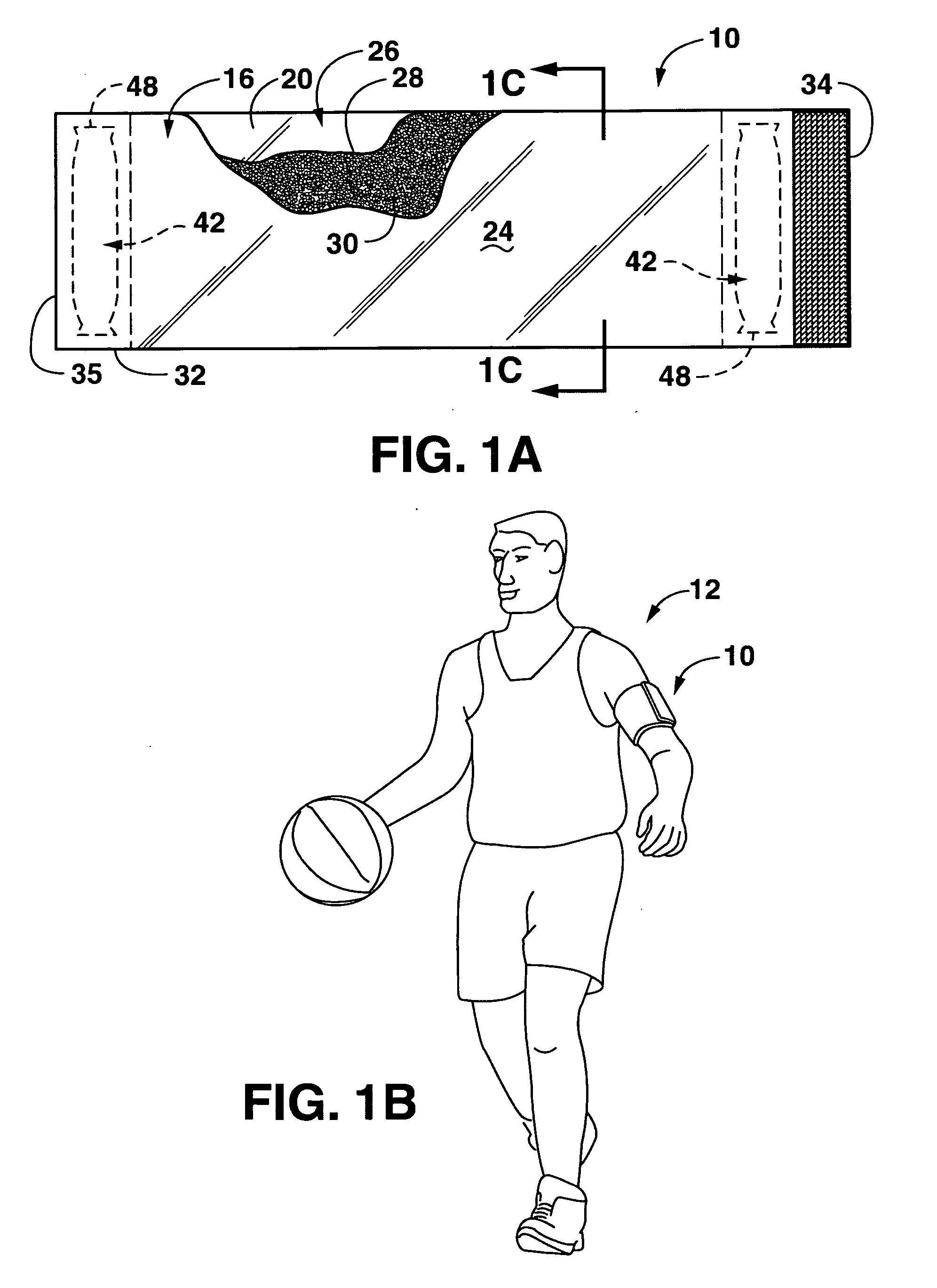
A warming device for placement against a body part or object includes a shell member having an outer face and an inner face disposed against a surface to be warmed. A first warming substrate is disposed within the shell member and is an absorbent web having a generally uniform application of a first warming composition applied thereto, the warming composition activated by contact with an aqueous liquid. An aqueous liquid source is disposed within the shell member and is separated from the first warming substrate by a barrier member. The device is activated by manual manipulation to breach the barrier member causing liquid from the liquid source to move within the interior space of the shell member to contact and activate the warming composition whereby a warming reaction is generated.

Description

BACKGROUND OF THE INVENTION[0001]Thermal heat wraps or packs are well known in the art for providing any manner of therapeutic or soothing warming to a person. For example, such devices are typically used to treat sports injuries, or used in various medical procedures to warm a patient. Warming packs are also used extensively in various “cold” recreational activities. For example, hunters or skiers may place such a device in their gloves or boots to keep the extremities warm in extreme cold conditions.[0002]WO 2004 / 105709 describes various types of self-warming skin care compositions that include a heat generating powder coated with a combination of oils and / or waxes to minimize a later reaction rate when the powder is combined with water, and to enable an increased duration heating cycle. The heat generated in the exothermic reaction of the powder with water warms the skin, enhances cleansing, and may provide improved blood circulation. The heat generating powder may be an inorgani...

Claims


Application Information

Patent Timeline
IPC IPC(8): A61F7/03
CPCA61F7/03A61F7/034A61F2007/0295A61F2007/0246A61F2007/0276A61F2007/0001
Inventor QUINCY, ROGER B.WRIGHT, ROBERT D.
Owner KIMBERLY-CLARK WORLDWIDE INC
Why Eureka
Try Eureka