Method of joining a plurality of conductor segments to form stator winding

a technology of conductor segments and stator windings, which is applied in the direction of stator/rotor bodies, manufacturing tools, and magnetic bodies, etc., can solve the problems of complex structure of arc welding system including the arrangement of inner and outer ground electrodes and new intermediate electrodes, and the complexity of installation of plurality of conductor segments in stator cores, so as to reduce the length of both ends and increase the number of turns of each stator winding. , the effect of high efficiency

Active Publication Date: 2008-06-26
DENSO CORP
View PDF13 Cites 19 Cited by
  • Summary
  • Abstract
  • Description
  • Claims
  • Application Information

AI Technical Summary

Benefits of technology

[0039]Rotary electric machines, such as alternators and high power output motors, to be installed in motor vehicles are particularly desired to downsize themselves with maintaining high efficiency. Thus, in the rotary electric machines to be installed in motor vehicles, it is required to install a plurality of stator windings of a stator coil in each slot of a stator core with a density as high as possible and to reduce the lengths of both ends of the stator coil from the stator core.
[0040]In order to meet the requirements, the plurality of stator windings of the stator coil are each made of a plurality of plate-like conductor segments with a width as narrow as possible, and / or the number of turns of each of the stator windings is more increased. In addition, for satisfying the requirements, the number of joints of the plurality of conductor segments is more increased, and / or pitches between the respective adjacent projecting ends of the conductor segments are more reduced.
[0041]To implement these various means to meet the requirements, the conductor-segment joining methods set forth above are required to easily, rapidly, and stably join pairs of projecting ends of different conductor segments with high accuracy and a high degree of flexibility capable of addressing the narrow pitches between the respective adjacent projecting ends of the conductor segments.
[0042]Even if the stator coil has the many-layer and many-row configuration, it is strongly desired to provide a method of easily and rapidly joining pairs of projecting ends of different conductor segments without increasing either the number of components or processes required to join them.
[0043]In view of the foregoing circumstances, an object of at least one aspect of the present invention is to provide a method of easily and rapidly joining pairs of projecting ends of a plurality of conductor segments without increasing either the number of components or processes required to join them.

Problems solved by technology

This arrangement step may cause the structure of the arc welding system including the arrangement of the inner and outer ground electrodes and the new intermediate electrodes to become complicated and great-sized.
This arrangement step may cause the installation of the plurality of conductor segments in the stator core to become complicated.

Method used


Image

  • Method of joining a plurality of conductor segments to form stator winding
  • Method of joining a plurality of conductor segments to form stator winding
  • Method of joining a plurality of conductor segments to form stator winding

Examples


first embodiment

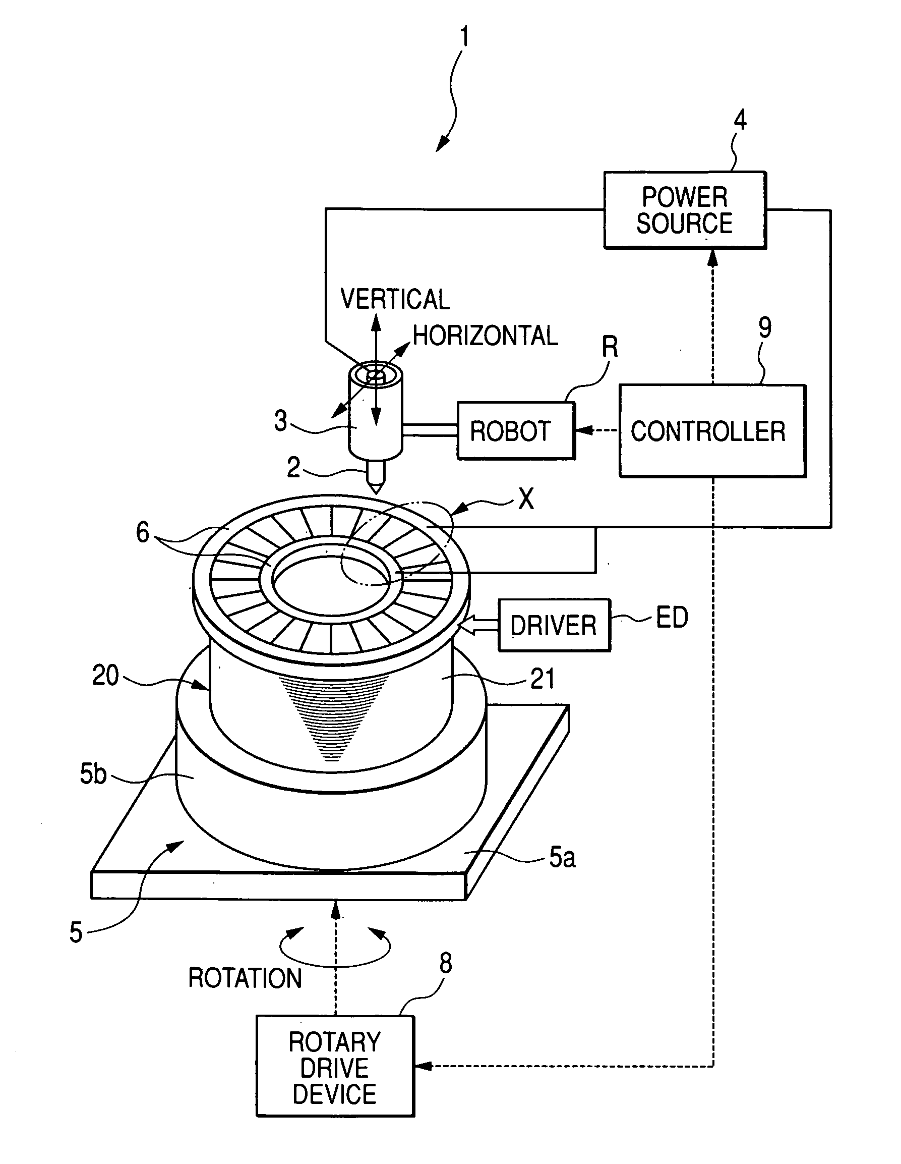
[0072]Referring to the drawings, in which like reference characters refer to like parts in several views, particularly to FIG. 1, there is illustrated a welding system 1. For example, as the welding system 1, a TIG welding system is used.

[0073]The welding system 1 includes a substantially cylindrical welding torch 3 integrated with a bar-shaped welding electrode (positive electrode) 2. The welding electrode 2 is supported in the welding torch 3 in its axial direction such that one end portion of the welding electrode 2 projects from one end wall of the welding torch 3.

[0074]The welding system 1 includes a welding power source 4 for supplying power to the welding electrode 2, and a supporting table 5 having a two dimensional mount surface 5a.

[0075]An annular cylindrical stator core 21 of a stator 20 is supported by an inner periphery of an annular cylindrical support 5b of the supporting table 5 fixedly mounted on the mount surface 5a; this stator 20 is a work to be welded.

[0076]The...

second embodiment

[0255]The second embodiment of the present invention will be described hereinafter with reference to FIG. 8. Like parts between the first and second embodiments, to which like reference characters are assigned, are omitted or simplified in description.

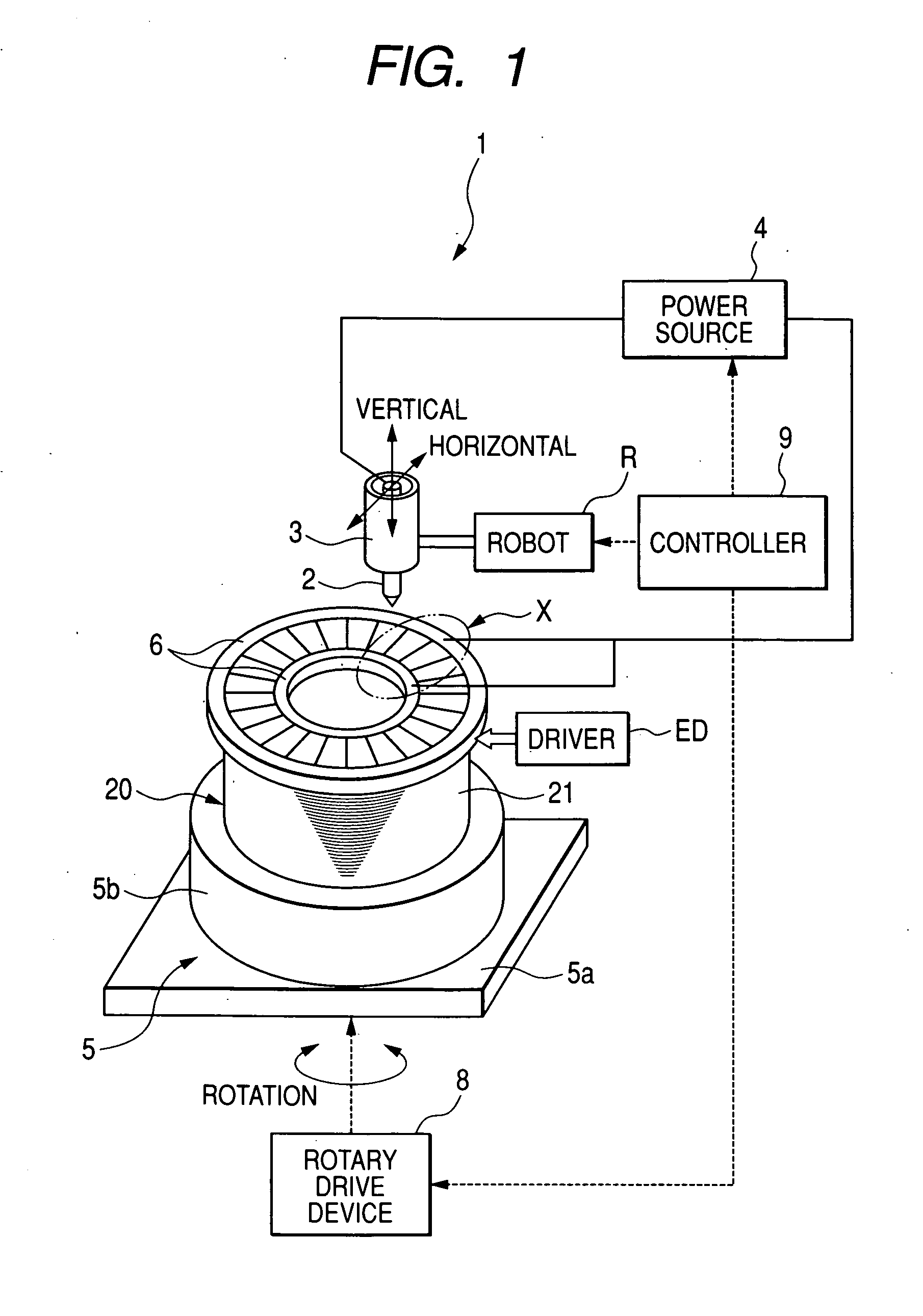
[0256]In the first embodiment, the conductor-segment joining method is applied to the stator coil 23 having the eight-layer and four-row configuration as illustrated in FIGS. 2 and 4.

[0257]In contrast, a conductor-segment joining method according to the second embodiment is applied to a stator coil 23X having a twelfth-layer and six-row configuration illustrated in FIG. 8.

[0258]As illustrated in FIG. 8, a first intermediate tip-end pair 15a10 composed of ninth tip end 151 and tenth tip end 152 and a second intermediate tip-end pair15a11 composed of eleventh tip end 153 and twelfth tip end 154 are located between the second tip-end pair 15a2 and the third tip-end pair 15a3.

[0259]In the configuration of the stator core 23X, the conductor...


PUM

PropertyMeasurementUnit
electrical conductionaaaaaaaaaa
electric conductionaaaaaaaaaa
lengthsaaaaaaaaaa

Abstract

In a method, a first electrode is moved to contact with first paired ends of first paired conductor segments. Next, a second electrode is moved opposing the first paired ends Electric conduction is established between the first electrode and the second electrode via the first paired ends of the first paired conductor segments to weld the first paired ends of the first paired conductor segments based on the electrical conduction therebetween. Next, the second electrode is moved opposing second paired ends of second paired conductor segments while the first electrode is kept in contact with the first paired ends. Electric conduction is established between the first electrode and the second electrode via the welded first paired ends and the second paired ends to thereby weld the second paired ends of the second paired conductor segments based on the electrical conduction therebetween.

Description

CROSS REFERENCE TO RELATED APPLICATIONS[0001]This application is based on Japanese Patent Application 2006-342830 filed on Dec. 20, 2006. This application claims the benefit of priority from the Japanese Patent Application, so that the descriptions of which are all incorporated herein by reference.FIELD OF THE INVENTION[0002]The present invention relates to methods of joining a plurality of conductor segments to form a stator winding of a stator; this stator is used for various rotational electric machines, such as alternators and motors.BACKGROUND OF THE INVENTION[0003]Rotary electric machines have been required to reduce the lengths (heights) between both stator coil ends of a stator from an annular cylindrical stator core thereof while increasing the winding packing factor of the stator. In order to meet the requirement, rotary electric machines, each of which installs therein an annular-shaped stator with a sequentially joined-segment stator coil, have been proposed.[0004]The se...

Claims


Application Information

Patent Timeline
Patent Type & Authority Applications(United States)
IPC IPC(8): H02K15/04B23K9/12
CPCH02K15/0081H02K15/064Y10T29/49009Y10T29/53143Y10T29/49012Y10T29/49071
Inventor HARA, SATORU
Owner DENSO CORP
Why Eureka
Try Eureka