Method for Controlling a Fuel Injector

a technology of fuel injector and internal combustion engine, which is applied in the direction of fuel injector pump, electric control, machine/engine, etc., can solve the problems and affecting the operation of the engine. , to achieve the effect of occupying more spa

Inactive Publication Date: 2008-06-26
VOLVO LASTVAGNAR AB
View PDF28 Cites 3 Cited by
  • Summary
  • Abstract
  • Description
  • Claims
  • Application Information

AI Technical Summary

Benefits of technology

[0004]An accepted solution to the problem described above has hitherto been to use a stronger plunger return spring. A disadvantage with a stronger return spring is that such a spring takes up more space. In modern diesel engines the space

Problems solved by technology

If the force of the return spring is not sufficiently great, there is a risk that the contact in the force transmission chain between the plunger and the driving cam lobe will be broken, with the result that damage can occur, for example, in the immediate area of the injector cam lobe corresponding to the maximum lift position of the plunger when the parts driven by the cam lobe are braked and the inertial forces

Method used


Image

  • Method for Controlling a Fuel Injector
  • Method for Controlling a Fuel Injector
  • Method for Controlling a Fuel Injector

Examples


Embodiment Construction

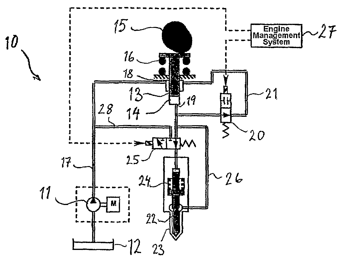
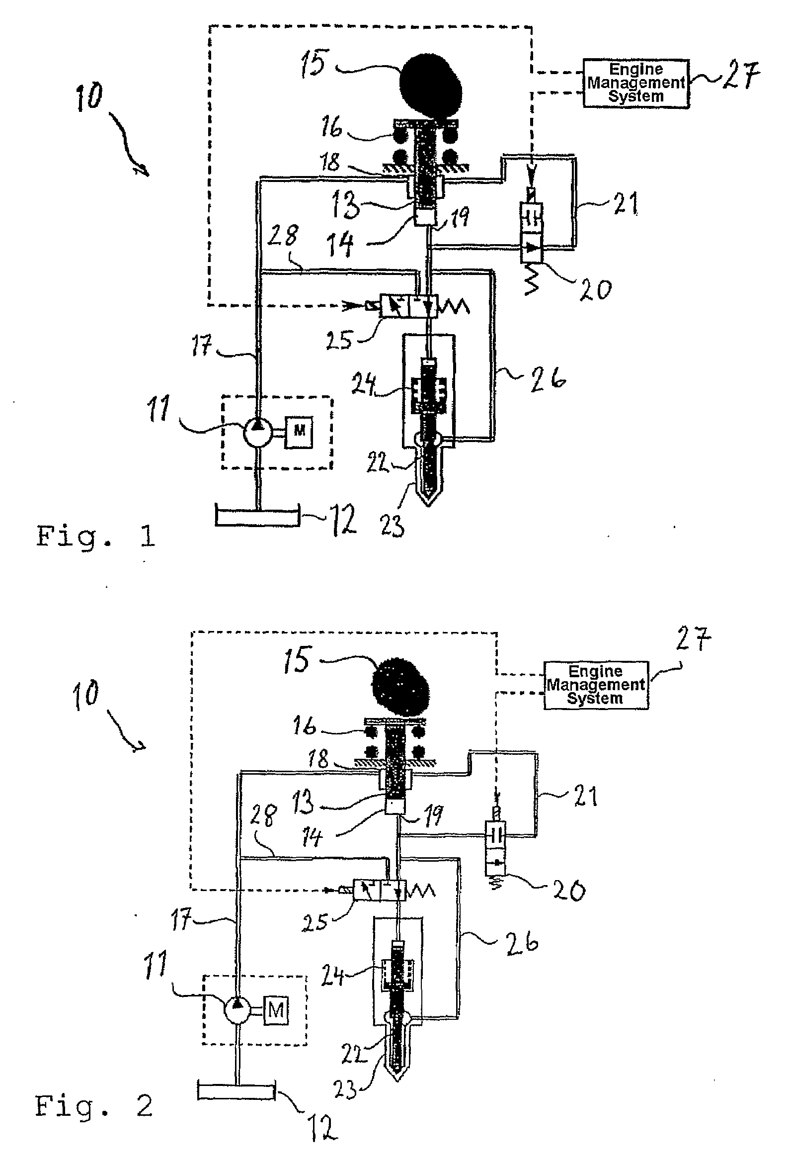
[0011]FIGS. 1 and 2 show schematic representations of a unit injector 10 of a type known in the art, which is fed with fuel by means of a pump 11, which draws it from a tank 12. The injector in a known manner comprises a plunger 13, which is driven to perform a reciprocating movement in a piston cylinder 14 by a camshaft 15 in opposition to the action of a compression spring 16 and any fuel pressure below the plunger. The contact between the camshaft lobe and the plunger can in reality be achieved directly by way of a cam-following roller, or in some other way, for example by way of a rocker arm.

[0012]The inlet end 18 of the piston cylinder 14 is connected to the pump feed line 17. The outlet end 19 of the piston cylinder 19 is connected to the inlet end 18 via an electrically controlled spill valve 20, which in its open position admits a flow via the circuit 21, that is to say the working of the plunger does not create any significant pressure build-up in the injector.

[0013]This pr...


PUM


Abstract

A method in an internal combustion engine for controlling a fuel injector of the unit injector type which includes a plunger that is driven by a rotating camshaft and during a working stroke generates a hydraulic pressure increase in the fuel. Pressure build-up is regulated by a spill valve the injection sequence is regulated by a needle control valve. The spill valve and the needle control valve are regulated in such a way that additional plunger retardation force is produced in a part of a working stroke in addition to the normal retardation force that is produced by the plunger return spring and the flow resistance in the injector.

Description

BACKGROUND AND SUMMARY[0001]The present invention relates to a method in a internal combustion engine for controlling a fuel injector of the unit injector type, which comprises a plunger which is driven by a rotating camshaft and during a working stroke generates a hydraulic pressure increase in the fuel, which is regulated with regard to the pressure build-up by a spill valve and with regard to the injection sequence by a needle control valve.[0002]In an internal combustion engine, such as a diesel engine with unit injectors, the injector plunger requires a strong return spring, in order to retard the plunger over a part of its working stroke. If the force of the return spring is not sufficiently great, there is a risk that the contact in the force transmission chain between the plunger and the driving cam lobe will be broken, with the result that damage can occur, for example, in the immediate area of the injector cam lobe corresponding to the maximum lift position of the plunger ...

Claims


Application Information

Patent Timeline
IPC IPC(8): F02M47/02
CPCF02D41/40F02M47/027Y02T10/44F02M59/462F02M59/102Y02T10/40
Inventor REMMELGAS, JOHAN
Owner VOLVO LASTVAGNAR AB
Why Eureka
Try Eureka