Moving Target System for Training In Marksmanship and Target Identification

a target identification and moving target technology, applied in the field of target identification training systems, can solve the problems of system disadvantage, constant target image of the shooter, waste of time, etc., and achieve the effect of improving the quality of shooter training

Active Publication Date: 2008-06-26
BLIEHALL JAMES CARL
View PDF32 Cites 10 Cited by
  • Summary
  • Abstract
  • Description
  • Claims
  • Application Information

AI Technical Summary

Benefits of technology

[0011]The inventive target systems of the present invention provides a moving target system for marksmanship and target identification training that overcomes the hereinafore-mentioned disadvantages of the heretofore-known devices and methods of this general type and that improves the quality of shooter training, makes such training more consistent by giving the target movements that mimic that of a human being—the movements are more random, non-synchronous, and / or non-repetitive. The movements of the inventive system are produced with a motor drive that can accept any type of target, such as a bull's eye, a circle, and other defined objects. The targets most often used in training law enforcement and military shooters depict a person. Thus, the system of the present invention can provide targets in the image of a person, whether presenting a weapon (a threat) or not presenting a weapon (no-threat or hostage).
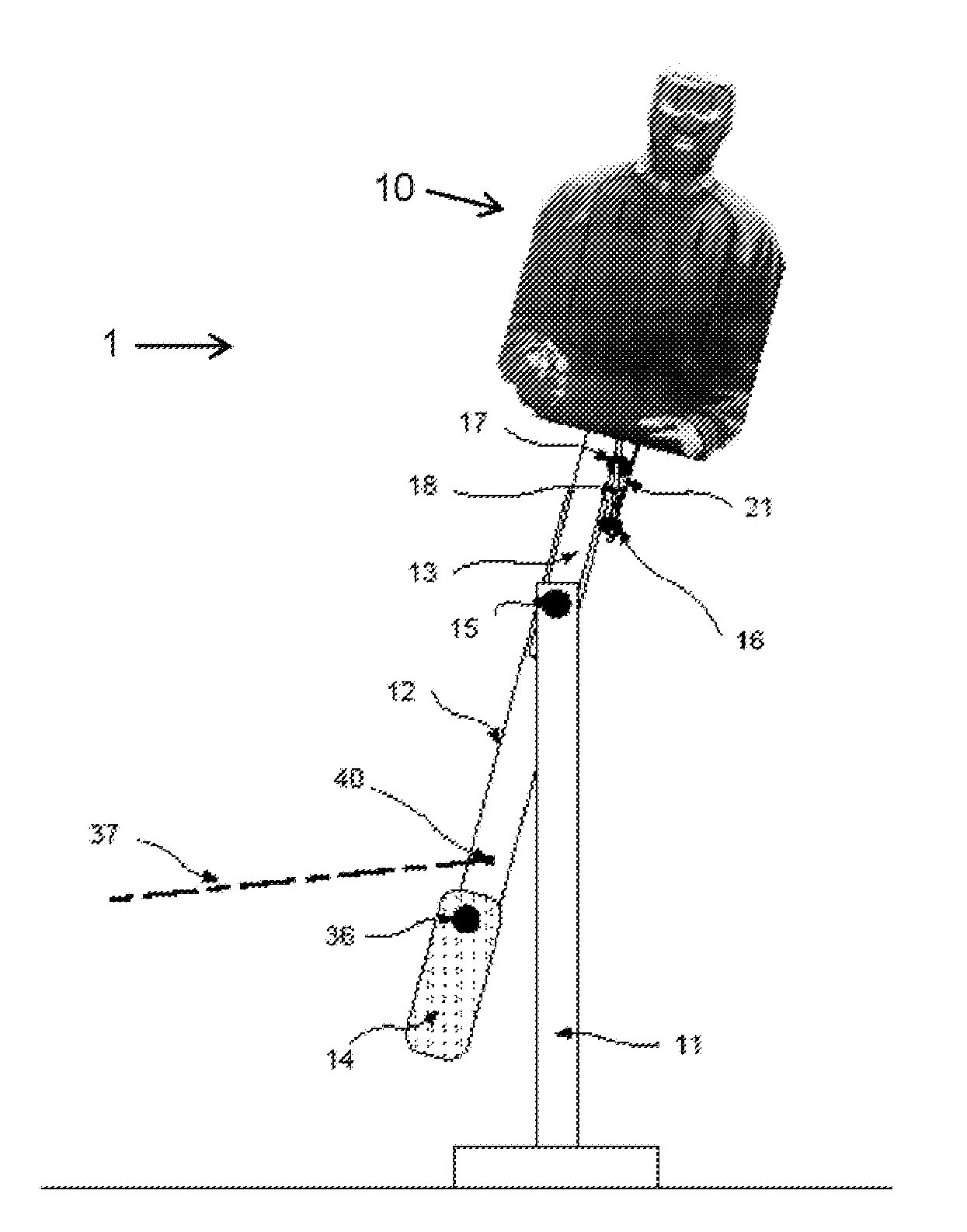
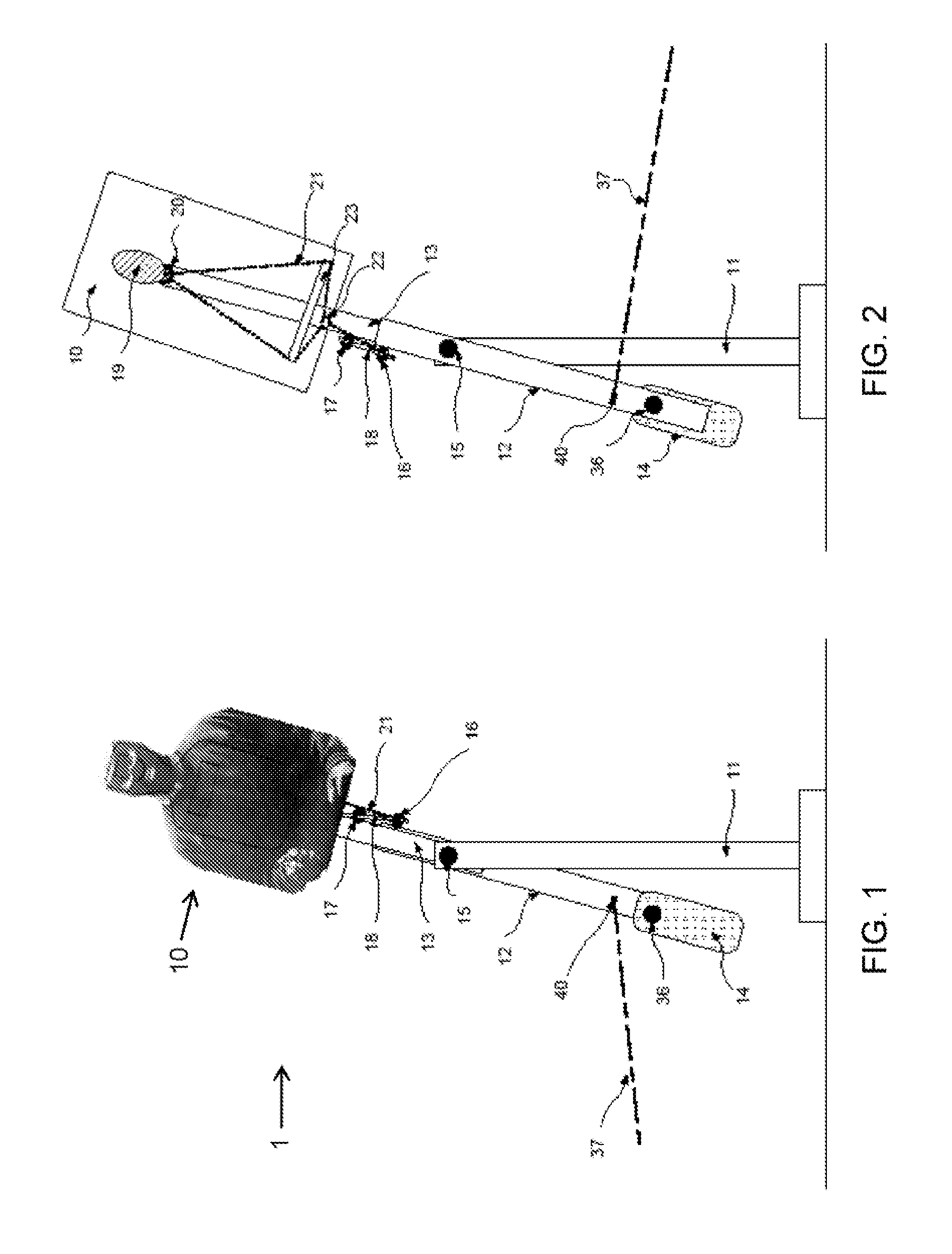
[0024]The crankshaft cranks are connected through a cord to targets having an adjustable counterweight, for example, at a bottom thereof. The target swings back and forth on a center axle but its movements are controlled by various measures. One control is effected with the speed of the motor driving the crankshaft; higher revolutions per minute translate into faster target arc movement rates. Another control is a position of the counterweight relative to the swing arm on which the target arm is mounted. If the counterweight is positioned directly in line with the target swing arm, the target movements will be more smooth and even. However, if the counterweight is positioned at progressively greater angles with respect to the swing arm, the target movements become more erratic and non-synchronous. Another factor influencing control is the duration of motor on time. If the motor drive is on continuously, the target movements will be more smooth and rhythmic. However, if the motor drive is turned on and off, whether periodically or randomly, the target will display erratic or chaotic movements. A further factor influencing target control is the length of a cord connecting the target swing arm to the crankshaft crank. If the cord between the motor and the crankshaft crank to which it is attached is shorter, the target will swing in a larger arc, following the movement of the crankshaft crank to which it is attached.
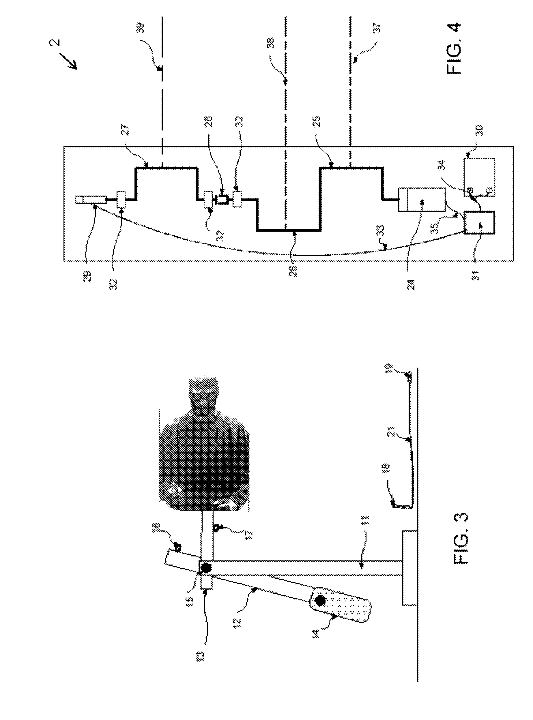
[0026]The image of the person on a printed target can have a hand visible to the shooter. This hand can contain a weapon, defining the target a “threat” target. The system of the present invention allows the system operator to remotely and instantly change the target threat status from a “threat” to a “no-threat” or from a “no-threat” to a “threat.” The target system has a selectable crank, which the operator can engage using a remote control. In use, the image of the weapon in the target's hand is covered by an obscuring medium (such as a piece of cardboard with a section of newspaper glued to it to depict a person holding a newspaper). A mechanical connector holds the obscuring medium in place over the target image's band (holding the weapon). The mechanical connector can be a large staple, Velcro, double-sided tape, a paper clip, a piece of wood with nails in it, or any other fastener that can be quickly removed with little force. The obscuring medium itself or the device being used to hold the obscuring medium to the target image is connected through a cord to the selectable crank on the crankshaft. When the operator energizes, for example, the push solenoid actuator using a remote control, the selectable crank is connected to the moving crankshaft with an engagement or locking mechanism. The continuously turning crankshaft now can turn the selectable crank and pull the obscuring medium off the front of the target or pull the contrivance holding the obscuring medium on the target face free from the target. The obscuring medium falls to the ground (or elsewhere) and the target reverts from a “no-threat” to a “threat” with the weapon now visible.
[0027]The system also allows the operator to change the “threat” target to a “no-threat” target. For example, an image of a hand or other non-lethal object is connected firmly over the weapon image on the target and an obscuring medium containing the image of a weapon (or weapon in a hand) is placed over the hand. Thus, while the weapon is visible, the shooter must engage the threat target. However, as soon as the target changes to a no-threat target—when the obscuring medium is removed and simulating the target having dropped their weapon—the shooter must cease fire. This is excellent training for the shooter because it prevents a shooting of a no-threat target.
[0028]The invention has a number of distinct advantages over prior art target systems. First, the system is able to mimic human movements, increasing the level of shooter training. Next, these unique movements are adjusted easily by the system operator and permit a variation of different skill levels. Simple, slow movements can be used for new shooters and more difficult, random and erratic movements can be used for advanced shooters. Further, the system can quickly change the status of the target from threat to no-threat or vice-versa, changes that occur in real life situations. This changeability requires the shooter to constantly be aware of the target's status, improving the skill set of the shooter. Additionally, the system is configured to require the shooter to accurately engage single or multiple moving targets. With an ability to present two targets at one time, one in front of the other, the shooter is given the opportunity to practice engaging a “threat” target while avoiding the no-threat target. The targets can be arranged with the no-threat target in front and the threat target behind or vice-versa. The system can even make both targets threat targets, requiring the shooter to engage both.
[0030]The system can be adjusted to present repeatable target movements to multiple shooters, thereby making it easier and more equitable when evaluating multiple shooters' capabilities. The system also can be operator adjusted to move the targets at controlled speeds and in predetermined and repeatable directions. Such features allow an instructor to work out a bad habit of a student shooter, for example.

Problems solved by technology

A first prior art target system places the target image in front of the shooter and is stationary and visible at all times. Such a system has the disadvantage of allowing the shooter to constantly see the target image as a threat.
Lastly, the target is stationary and does not mimic the motions a real human person would take if they were actually shooting back.
This system has the same disadvantages of the first target system described above.
This system has a disadvantage in that the shooter knows before the target image is rotated that when presented it will be a threat target; he shooter knows the target is a threat because the target is inserted in the turning device by the shooter and the image of the target is known to be a threat.
It would be a waste of time.
This system has the same disadvantages of the first target system described above.
This system has a disadvantage because it is limited to making stationary targets appear and disappear from view at the same location.
This system also has the disadvantages of the first target system described above.
This kind of target presentation is a challenge to the shooter because the target moves in an arc.
The disadvantage of this system lies in the fact that the movement of the target is controlled by a cord that is attached to the counterweight.
This system also experiences the disadvantages described with respect to the first system above.

Method used


Image

  • Moving Target System for Training In Marksmanship and Target Identification
  • Moving Target System for Training In Marksmanship and Target Identification
  • Moving Target System for Training In Marksmanship and Target Identification

Examples


Embodiment Construction

[0047]As required, detailed embodiments of the present invention are disclosed herein; however, it is to be understood that the disclosed embodiments are merely exemplary of the invention, which can be embodied in various forms. Therefore, specific structural and functional details disclosed herein are not to be interpreted as limiting, but merely as a basis for the claims and as a representative basis for teaching one skilled in the art to variously employ the present invention in virtually any appropriately detailed structure. Further, the terms and phrases used herein are not intended to be limiting; but rather, to provide an understandable description of the invention.

[0048]Embodiments herein can be implemented in a wide variety of ways using a variety of technologies that enable random movement of targets. One embodiment of the present invention utilizes a target system 1 that mimics human movement. Turning now to FIGS. 1 to 3, there is shown a shooter's target 10 directly moun...


PUM


Abstract

A target moving configuration includes a weighted base, a shooter's target, a target-moving assembly rotationally connected to the base and a hinge pivotally connecting the target thereto. A target-fall control device operatively connects the hinge to selectively pivot the target when activated. The control device has a balloon, a lock with a removable key, and a pull cord connecting the balloon to the key, which cord holds the key in the lock while the balloon is intact. A target motion device has a drive shaft, a drive cord connected to the target moving assembly and the drive shaft. An electric motor is connected to the drive shaft for rotating the drive shaft. A controller is operable to selectively and randomly power the motor to, thereby, move the target movement arm with respect to the base. Multiple targets and assemblies are provided and connected to the drive shaft for independent movement.

Description

BACKGROUND OF THE INVENTION[0001]1. Field of the Invention[0002]This invention relates in general to target systems and, specifically, to a marksmanship and target-identification training system using moving targets.[0003]2. Description of Related Art[0004]The target systems being used to train law enforcement and military shooters today are predominantly one of the following enumerated types.[0005]A first prior art target system places the target image in front of the shooter and is stationary and visible at all times. Such a system has the disadvantage of allowing the shooter to constantly see the target image as a threat. The system gives the user no opportunity to recognize the status (threat or no threat) of the target image. Because there is no requirement to recognize the status of the target image, the target is always recognized by the shooter as being a threat. The shooter simply draws their weapon as quickly as possible and shoots the target image as accurately as possibl...

Claims


Application Information

Patent Timeline
Patent Type & Authority Applications(United States)
IPC IPC(8): A63B63/00
CPCA63B63/06F41J7/06F41J7/04A63B2063/065
Inventor BLIEHALL, JAMES
Owner BLIEHALL JAMES CARL
Why Eureka
Try Eureka