

Dynamically configurable logic gate using a non-linear element
- Summary
- Abstract
- Description
- Claims
- Application Information
AI Technical Summary
Benefits of technology
Problems solved by technology
Method used
Image

Examples
first embodiment
of Dynamically Configurable Logic Gate
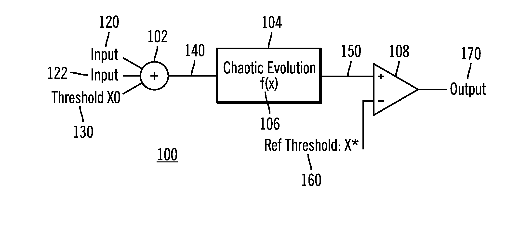
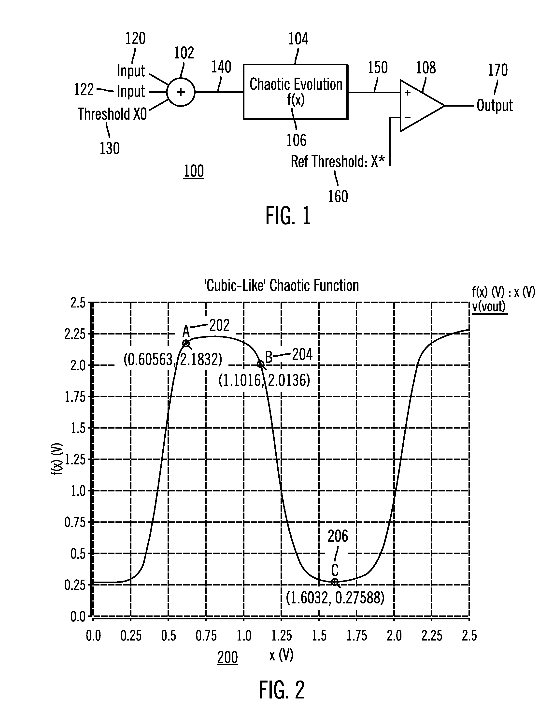
[0051]Turning now to FIG. 1, shown is a schematic diagram illustrating one embodiment of a high-level circuit architecture 100 for a dynamically configurable logic gate, according to the present invention. In this implementation multiple chaotic evolutions are not necessary, and only a single chaotic evolution is necessary between the input and the output threshold circuit. By implementing only a single chaotic evolution, this greatly simplified the circuit to an input summer or input adder 102, the nonlinear element or chaotic circuit 106, and an output comparator 108.
[0052]As shown in FIG, 1, the dynamically configurable logic gate includes an input summer or input adder 102. The input adder 102 receives three signals: an input first signal 120; a second input signal 122; and a first threshold signal 130. The input adder 102 combines the three signals 120, 122, and 130 to form a summed signal 140, which is the input into the nonlinear element ...
second embodiment
Of Dynamically Configurable Logic Gate
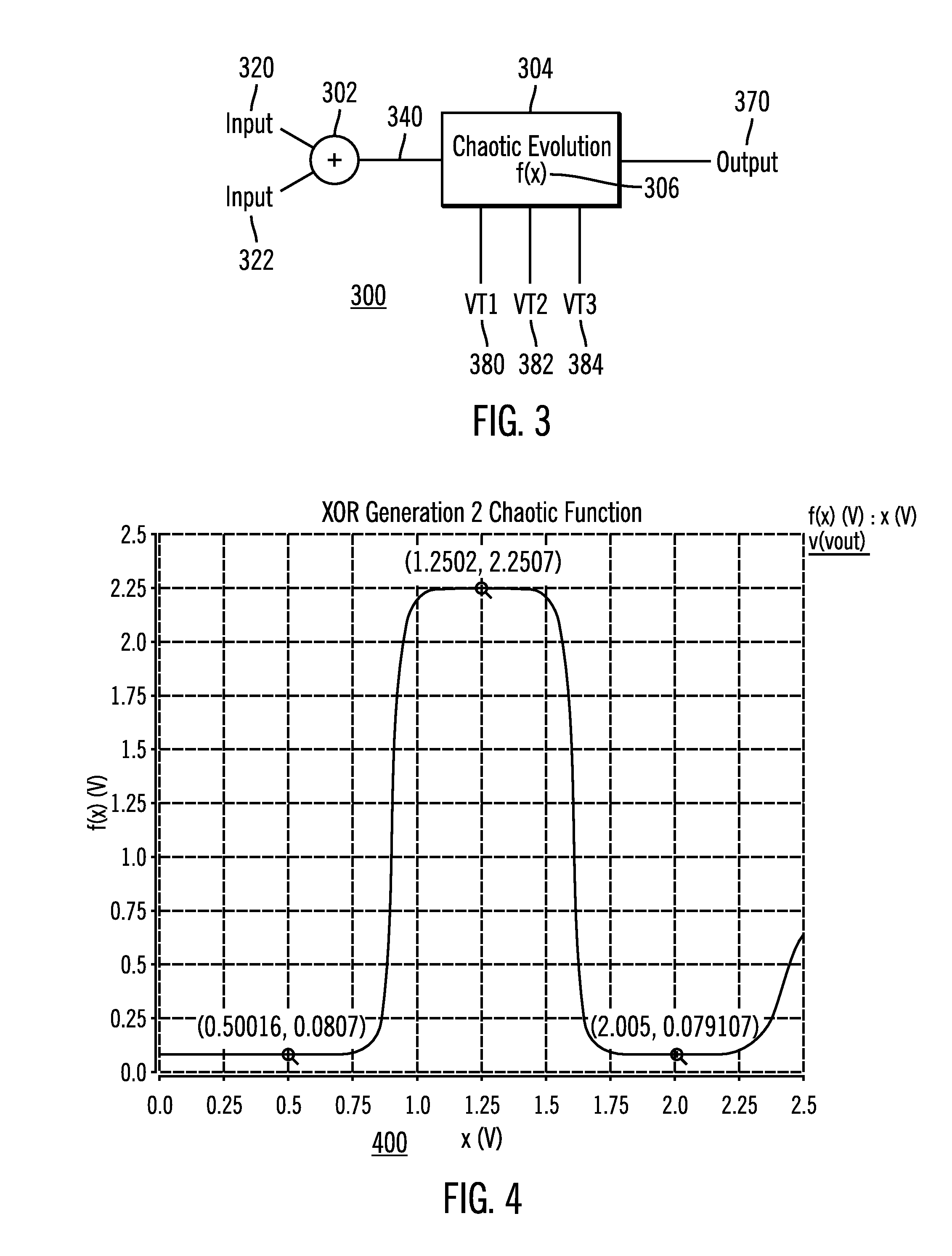
[0056]FIG. 3 is a schematic diagram illustrating another embodiment of a high level circuit architecture 300 for a dynamically configurable logic gate, according to the present invention. An input summer or input adder 302 accepts two input signals 320 and 322 to form a summed signal 340. The summed signal is the input to the nonlinear or chaotic element 304 with nonlinear function 306 which is configured to apply the nonlinear function 306 to the summed signal 340 to produce a nonlinear output signal 370. The nonlinear function is 306 and / or the dynamic regions upon which the summed signal 340 is mapped is changed in response to change of at least one of the reference signals 380, 382, and 384. The nonlinear output signal 370 corresponds to a plurality of different logic gates responsive to adjusting one or more of the reference signals 380, 382, and 384 and / or the nonlinear function 306.
[0057]In this circuit architecture 300 the reference sign...
third embodiment
of Dynamically Configurable Logic Gate
[0061]In this embodiment, the power is further reduced using an all digital CMOS implementation for the dynamically configurable logic gate. The major elements with the other embodiments of the dynamically configurable logic gate are present in this embodiment. The input summer provides the count of the inputs represented as a state space. The configuration operates as the threshold mechanism to change the mapping of the input state space to the chaotic evolution. The nonlinear or chaotic evolution provides the non-linear function to convert to the output. Because of the full digital nature, the static power is reduced to substantially zero.
[0062]FIG. 5 is a schematic diagram illustrating another embodiment of a high level circuit architecture 500 for a dynamically configurable logic gate, according to the present invention. An input summer or input adder 502 accepts three input signals 520, 522 and 524 to form a digital state output signals 530...
PUM
 Abstract
Description
Claims
Application Information