Exhaust-gas turbine in an exhaust-gas turbocharger

a technology of exhaust gas turbine and turbocharger, which is applied in the direction of liquid fuel engines, machines/engines, reaction engines, etc., to achieve the effect of discharging the exhaust-gas counterpressure and improving the overall efficiency of the turbin

Inactive Publication Date: 2008-06-26
FLEDERSBACHER PETER
View PDF2 Cites 15 Cited by
  • Summary
  • Abstract
  • Description
  • Claims
  • Application Information

AI Technical Summary

Benefits of technology

[0014]As the contour sleeve openings forming a bypass passage extending around the turbine rotor are arranged at a point axially within the turbine guide vane structure, exhaust gas bypassing the turbine rotor is subjected to spin as it enters the turbine outlet duct, which improves the overall efficiency of the turbine. In addition, when the axial slide is closed in the direction of the blocking position, an effective turbine inlet cross section remains as the slide comes to rest over that part of the turbine wheel inlet which faces toward the bearing side of the turbine. In this way, the delimiting face which faces toward the bearing side of the flow duct is axially movable and the delimiting face which faces toward the outlet duct is stationary.
[0015]With the design according to the invention, it is very easily possible to provide a discharge function which is obtained for example in that, when the axial slide is in a retracted position—that is to say when the turbine inlet cross section is enlarged—a discharge path from the inlet channel to the outlet duct in the exhaust-gas turbine is opened, via which the exhaust gas can flow to the outlet duct and substantially bypass the turbine wheel blades. A so-called internal discharge is realized in this way, which can be activated for example at high engine rotational speeds in order to dissipate the exhaust-gas counterpressure. The discharge quantity can be controlled in a stepless fashion by changing the axial position of the axial slide.
[0017]In one preferred embodiment, the axial slide is seated on, and is mounted so as to be movable on, a contour sleeve which encases the turbine wheel. Said contour sleeve can, since it is fixedly and immovably mounted in the turbine housing, be adapted in the best possible way to the contour of the turbine wheel, so that gaps between the turbine wheel blades and the inner side of the contour sleeve are minimized, and loss of gas flow can be largely avoided. In a further advantageous embodiment, the contour sleeve has at least one discharge opening, which is opened at least when the axial slide is in the maximum open position, so that exhaust gas can pass directly from the inlet channel into the outlet duct. The guide vane structure advantageously extends axially over the discharge opening in the contour sleeve, so that, even when the axial slide is retracted and the discharge opening is opened, the outflowing exhaust gas must first pass through the guide vane structure where a swirl is imparted to it by the guide vane structure, which improves the flow conditions in the turbine outlet, as a result of which an increase in efficiency is obtained even in by-pass discharge operation of the turbine.

Problems solved by technology

With said multiple deflection of the exhaust gas, it is not possible to impart a swirl to the exhaust gas which would improve the gas flow through the turbine and therefore also the turbine efficiency.

Method used


Image

  • Exhaust-gas turbine in an exhaust-gas turbocharger
  • Exhaust-gas turbine in an exhaust-gas turbocharger
  • Exhaust-gas turbine in an exhaust-gas turbocharger

Examples


Embodiment Construction

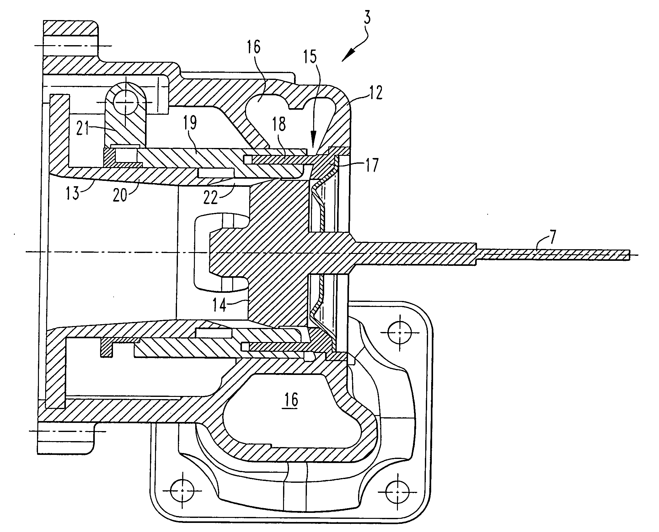
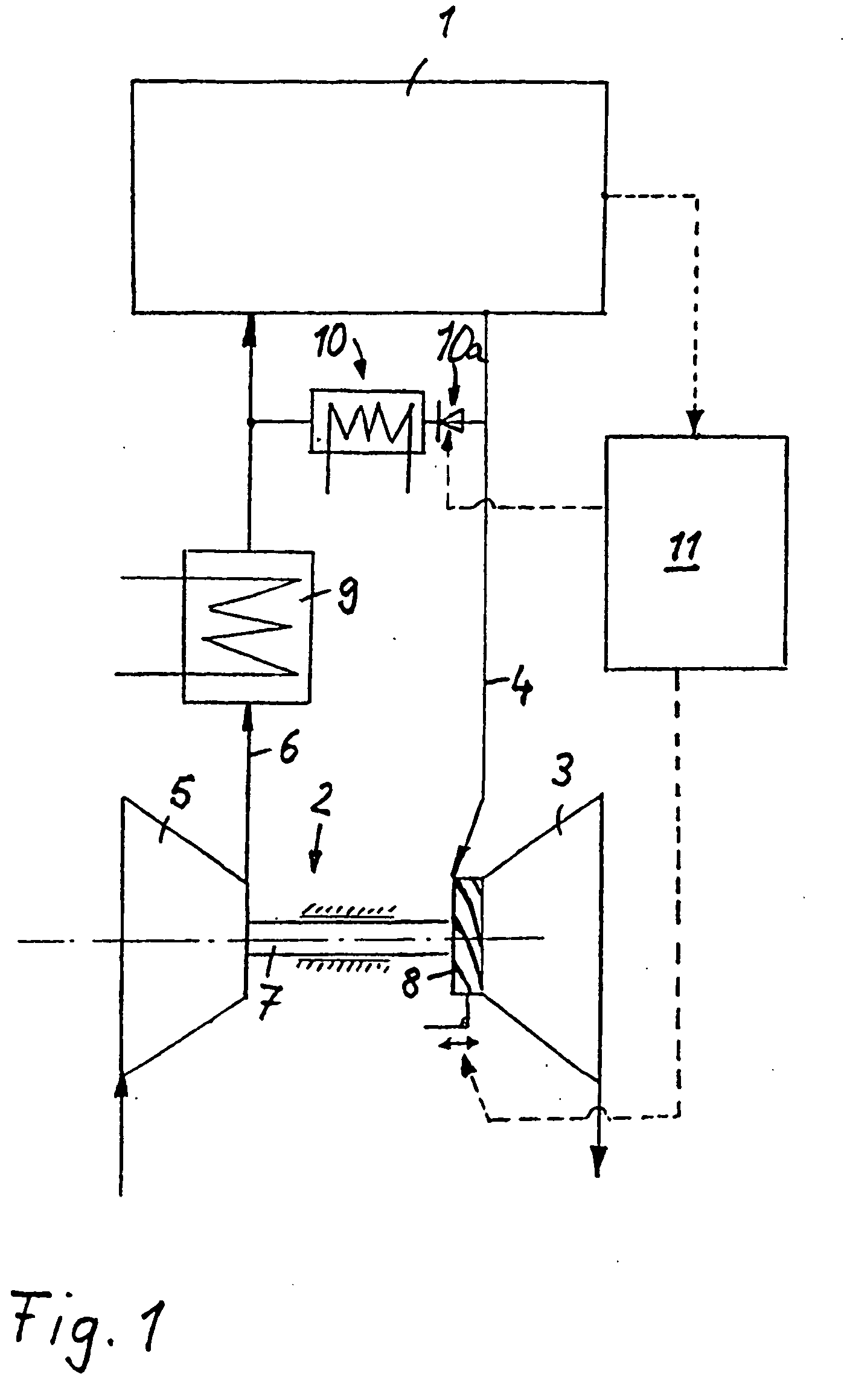
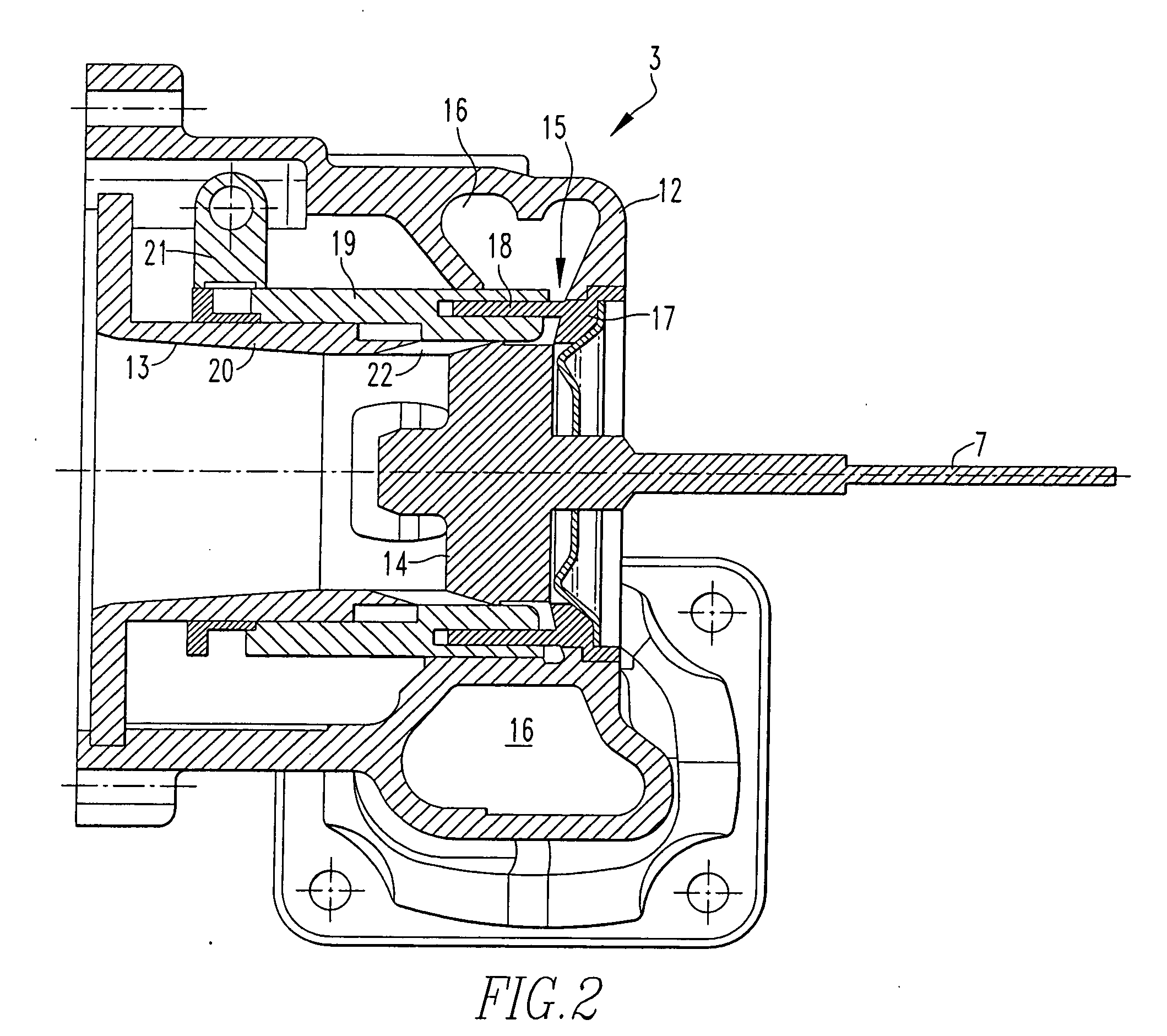
[0026]The internal combustion engine 1 which is illustrated in FIG. 1 and which is in particular a spark-ignition engine, though it may also be a diesel internal combustion engine, is provided with an exhaust-gas turbocharger 2 which comprises an exhaust-gas turbine 3 in the exhaust strand 4 of the internal combustion engine and a compressor 5 in the intake tract 6. Rotatably mounted in the exhaust-gas turbine 3 is a turbine wheel which is driven by the pressurized exhaust gases of the internal combustion engine. Said rotational movement is transmitted via a shaft 7 to the compressor wheel in the compressor 5, whereupon combustion air at ambient pressure is sucked in and compressed to an increased charge air pressure.

[0027]The exhaust-gas turbine 3 is provided with a variable turbine geometry 8 which is embodied in particular as a guide vane structure, which is disposed in the effective turbine inlet flow cross section. An interacting axial slide is movably disposed in the turbine, ...


PUM


Abstract

In an exhaust-gas turbine of an exhaust-gas turbo-charger including a turbine wheel which is rotatably supported in a housing and to which exhaust gas can be supplied via an inlet channel and discharged out of the exhaust-gas turbine via an outlet duct, wherein a guide vane structure and an axial slide which interacts with the latter, are disposed in the turbine inlet at the transition from the inlet channel to the turbine wheel, the guide vane structure is fixedly mounted with respect to the housing and the axial slide is arranged at the turbine outlet side and is movably supported on an outlet duct contour sleeve and provided with an axial opening for accommodating the guide vane structure, and the contour sleeve includes openings which conduct exhaust gas from the inlet channel directly to the outlet duct and which are arranged so that they are covered by the axial slide when the axial slide is moved out of its open position, the guide vane structure extending axially over the contour sleeve openings so as to impart a swirl to the exhaust gas being discharged via the contour sleeve openings when the slide member is in an open position.

Description

[0001]This is a Continuation-in-Part Application of pending international application PCT / EP2006 / 005433 filed Jun. 7, 2006 and claiming the priority of German application 10 2005 027 080.8 filed Jun. 11, 2005.BACKGROUND OF THE INVENTION[0002]The invention relates to an exhaust-gas turbine in an exhaust-gas turbocharger having a turbine wheel which is rotatably supported in a housing including an inlet channel for supplying exhaust gas to the turbine for driving the turbine wheel.[0003]Document EP 0 654 587 B1 discloses an exhaust-gas turbocharger for an internal combustion engine, whose exhaust-gas turbine is arranged in the exhaust strand of the internal combustion engine and whose compressor is arranged in the intake tract. The turbine wheel of the exhaust-gas turbine is driven by the pressurized exhaust gases and its rotational movement is transmitted via a shaft to the compressor wheel of the compressor. Combustion air drawn in at ambient pressure is compressed by the compressor...

Claims


Application Information

Patent Timeline
Patent Type & Authority Applications(United States)
IPC IPC(8): F02B37/24F04D15/00
CPCF01D17/143F02C9/18F02C6/12
Inventor FLEDERSBACHER, PETERHIRTH, TORSTENLEHMANN, HANS-GEORGSIEDLE, VOLKERSUMSER, SIEGFRIED
Owner FLEDERSBACHER PETER
Why Eureka
Try Eureka