
Device And Process For Coating Workpieces

a technology for workpieces and coatings, applied in the direction of liquid/solution decomposition chemical coatings, chemical coatings for solid/suspension decomposition, medical atomisers, etc., can solve the problems of large amount of varnish, high loss of varnish, and inability to apply varnish with particularly good edge definition

Inactive Publication Date: 2008-06-26
HOMAG HOLZBEARBEITUNGSSYST
View PDF124 Cites 14 Cited by
  • Summary
  • Abstract
  • Description
  • Claims
  • Application Information

AI Technical Summary

Benefits of technology

[0005]It is therefore an object of the invention to provide a device of the aforementioned type, which allows a simple yet precise and high-quality coating of workpieces, in particular in the region of narrow or partial surfaces, as well as to provide a process herefor.
[0009]The provision of at least one micro-nozzle makes it possible to apply the curable mass to the respective surface section of the workpiece in a targeted and edge-defined manner, without a complicated or expensive arrangement being required herefor. Although the process for ejecting the curable mass out of the micro-nozzles can, in principle, be actuated and controlled in any manner within the scope of the present invention, a main objective of the invention is that the application means comprises at least one micro-valve. Thus, it has become apparent that this type of supply and control of the curable mass in conjunction with an associated micro-nozzle is particularly suitable for varnishes and similar coating substances since a precise and simple controllability with a good response behaviour is obtained. The respective micro-valve furthermore prevents undesired curing of the available, curable mass with low maintenance costs and a long service life.
[0010]According to an embodiment of the invention, it is provided that the application means has at least one pressurized store of curable mass. This allows for particularly good reaction behaviour and a high throughput of the device according to the invention since just one micro-valve has to be opened by a suitable current pulse or the like for a coating process.
[0011]It can thereby be sufficient in many cases that the pressurized store has a comparatively low volume and that, in addition, an actual storage container is provided, which supplies the pressurized store with curable mass and does not necessarily have to be under pressure itself. On the other hand, the pressurized store can also have a large volume and / or can be arranged for the most part at a position which is disposed at a distance from the respective micro-nozzle. The pressurized store can thereby be loaded, e.g., by an injection piston, which defines a desired pressure and can also ensure the removal of air bubbles or the like so as to obtain a high setting accuracy of the pressure and the ejection amount. It is moreover possible to deduce that there are possible clogged micro-nozzles by way of such an injection piston.
[0013]Within the scope of the present invention, the micro-valves can be designed in various different manners, with the use of solenoid micro-valves having proved to be particularly advantageous since they can be controlled and operated in a particularly easy and precise manner.
[0018]The smoothing means can, as will become more clear from the detailed description below, be formed in different ways, e.g. as a thermal-transfer smoothing means. It is achieved thereby that the workpiece surface is sealed and a swelling of the material is avoided. Furthermore, by introducing heat, the subsequent curing of a curable material is assisted in many cases. Finally, the curable mass can no longer penetrate the material, or can only penetrate it to a lesser extent, which leads to a lower consumption of curable mass.

Problems solved by technology

In this method, however, the varnish coating cannot be applied with particularly good edge definition due to the removal of the varnish by suction and the air turbulence.
Generally, a large amount of varnish is in the circulation of the Vacumat device.
High losses of varnish occur during a change of paint or varnish due to the necessary rinsing processes of the system components.
The Vacumat technology itself has high energy consumption due, on the one hand, to the generation of the vacuum and, on the other, to the power which has to be supplied to dry the varnish, and the system costs are relatively high.
This leads to high material waste.
A further disadvantage is the storage of the many different decorations required that match the decorative surface as well as the relatively high set-up times for changing a decoration.

Method used


Image

  • Device And Process For Coating Workpieces
  • Device And Process For Coating Workpieces
  • Device And Process For Coating Workpieces

Examples


Embodiment Construction

[0025]The preferred embodiments of the present invention are described in detail below with reference to the accompanying drawings.

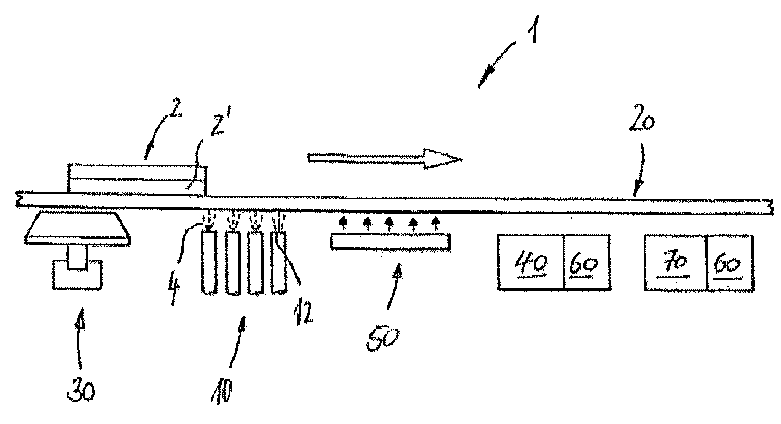
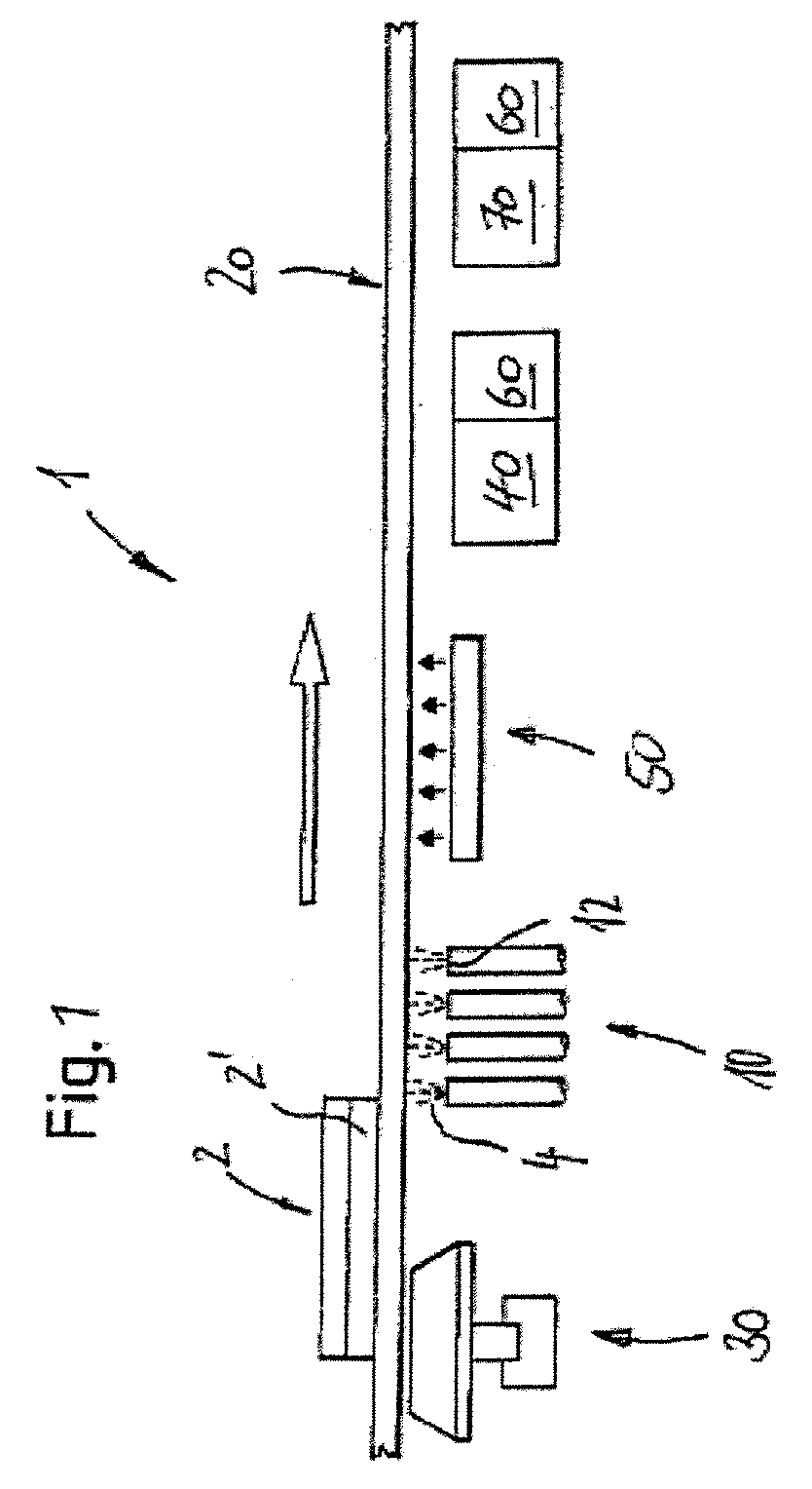
[0026]FIG. 1 schematically shows a coating device 1 as a preferred embodiment of the present invention. The device is used for coating and, optionally, also for decorating workpieces 2, which can be, e.g., flooring panels, consisting at least partially of wood, wood-based materials, synthetic material or, optionally, also varnish or the like. It should be noted, however, that the device 1 according to the invention is also suitable for coating different workpieces 2, even though the device is primarily intended for the applications mentioned above.

[0027]In the present embodiment, the device 1 comprises a conveyor means 20 which is designed as conveyor belt or conveyor table and can convey the respective workpieces 2 in a transport direction indicated by an arrow. Although the present embodiment thus relates to a so-called through-put machine, it should b...


PUM

PropertyMeasurementUnit
Diameteraaaaaaaaaa
Diameteraaaaaaaaaa
Diameteraaaaaaaaaa

Abstract

The invention relates to a device for coating workpieces which preferably consist at least partially of wood, wood-based materials, synthetic material or the like, said device comprising an application means for applying a curable mass, in particular a varnish, and a conveying device for causing a relative movement between said application means and the respective workpiece. The device according to the invention is characterized in that said application means has at least one micro-nozzle for applying said curable mass, and preferably at least one micro-valve.

Description

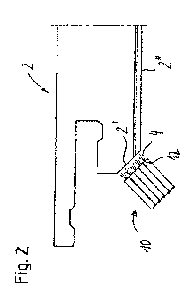
FIELD OF THE INVENTION[0001]The invention relates to a device for coating workpieces which preferably consist at least partially of wood, wood-based materials, synthetic material or the like, according to the preamble of claim 1 as well as to a process using this device.PRIOR ART[0002]Various techniques are known for coating workpieces which consist, e.g., at least partially of wood, wood-based materials, synthetic material or the like. A requirement recently made in the field of flooring production is to coat and decorate, in the case of flooring panels such as ready-to-use parquet or laminate, a so-called “mini-chamfer”. The arrangement of such a mini-chamfer 2′ on a flooring panel (workpiece) 2 is schematically shown, purely as an example, in FIG. 3.[0003]The mini-chamfer is normally produced by milling the respective flooring panel. Before being decorated (e.g. printed on), the milled surface must be provided with a coating, e.g. a primer. This is presently often carried out usi...

Claims


Application Information

Patent Timeline
IPC IPC(8): B05D7/08B05D1/02B05B9/04
CPCB05B13/00B05C9/14B41J11/002B41J11/0015B41J3/407B27D5/006B41J11/00214B41J11/00216
Inventor GAUSS, ACHIMALBRECHT, LUDWIGFREY, KARL
Owner HOMAG HOLZBEARBEITUNGSSYST
Learn More