
Transmission with resistance torque control

a technology of transmission and torque control, applied in the direction of hybrid vehicles, gearing, transportation and packaging, etc., to achieve the effect of increasing efficiency and increasing efficiency

Inactive Publication Date: 2008-06-26
TORVEC INC
View PDF28 Cites 3 Cited by
  • Summary
  • Abstract
  • Description
  • Claims
  • Application Information

AI Technical Summary

Benefits of technology

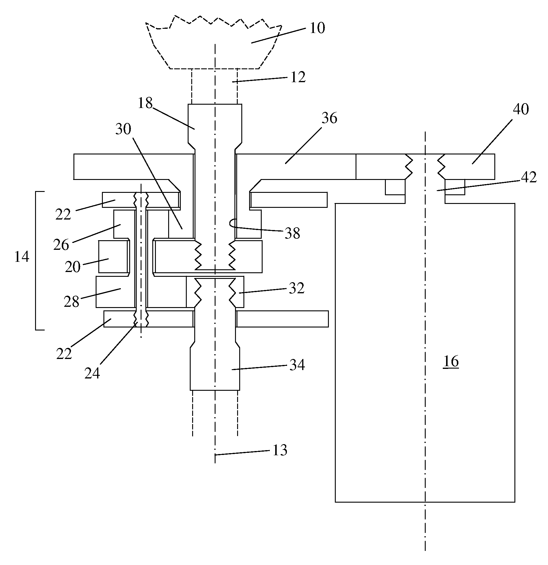
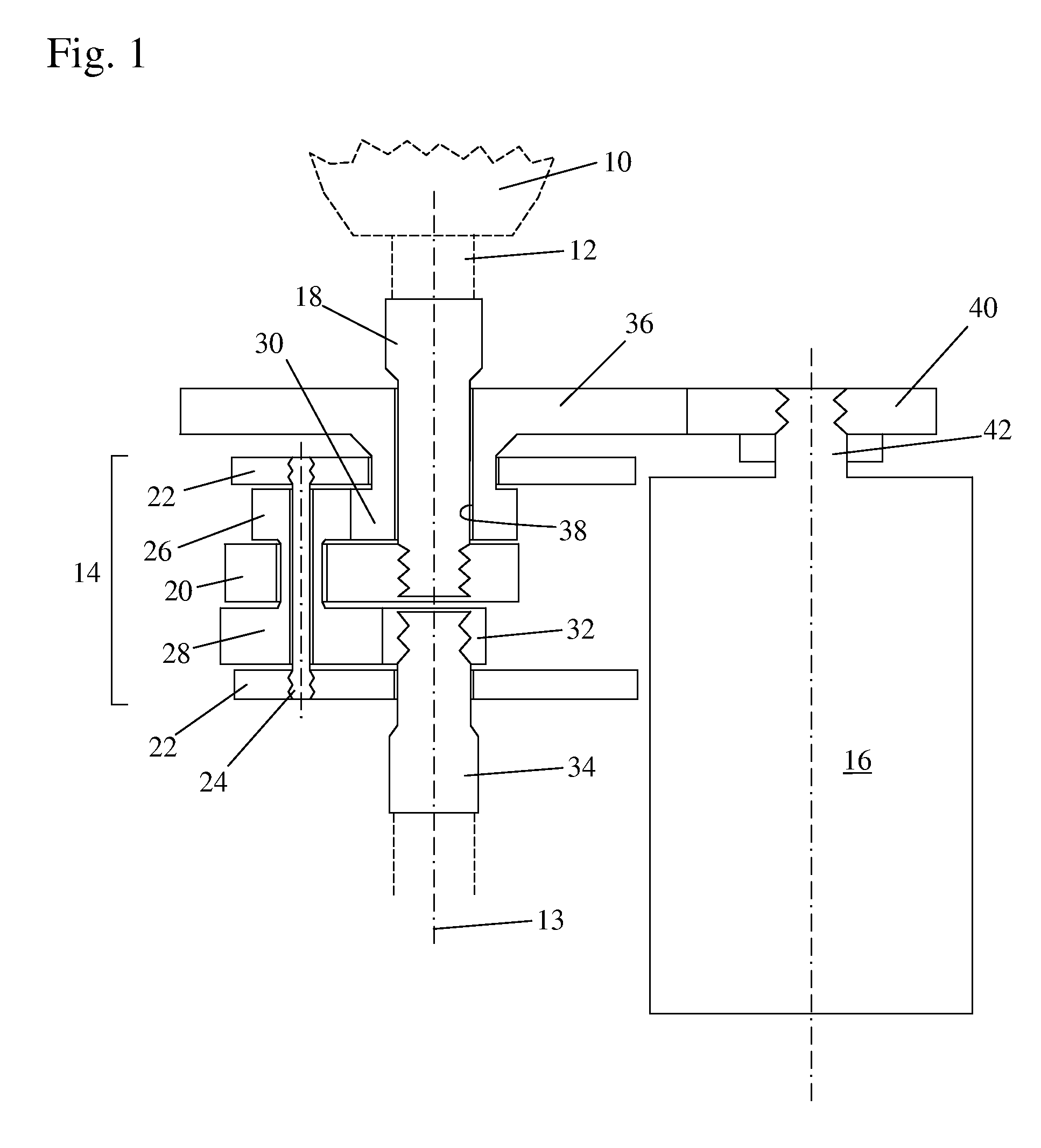
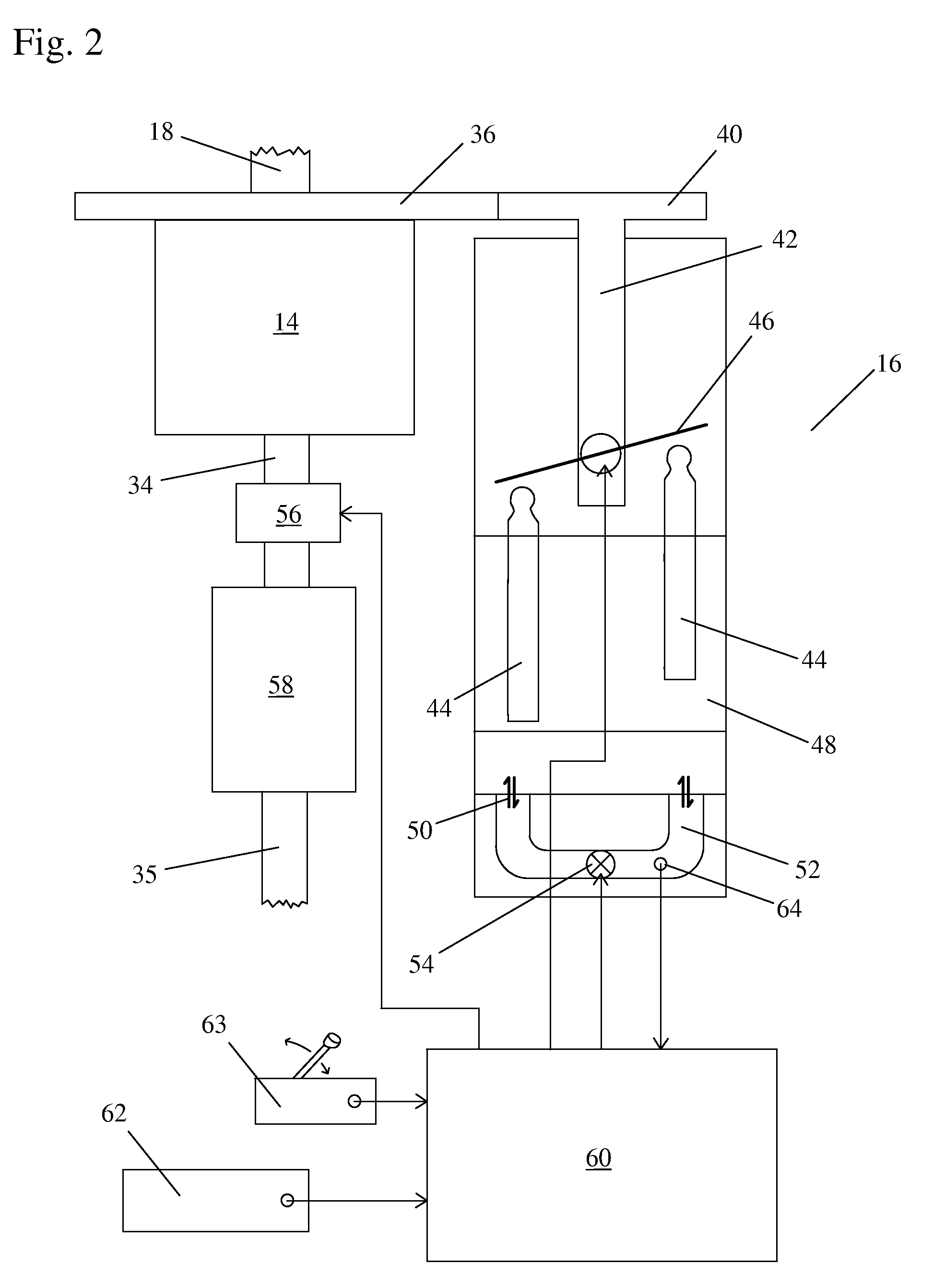
[0016]In a first embodiment, the rotary control device is a hydraulic jack machine having a drive shaft connected to an adjustable swash plate and having input and output ports connected through a very minimal fluid passage that is closed by a controlled pressure valve. [NOTE: The term “hydraulic jack” is used herein to denote a hydraulic transducer that provides no propelling motion whatsoever but rather is used for no other reason than to create a controlled resistive torque in the form of hydraulic pressure.] This single hydraulic jack machine generates resistance torque during vehicle acceleration but places negligible load on the vehicle's engine during start-up, engine idle, and vehicle cruising. Also, the operation of this single hydraulic machine omits the hydraulic pump that is conventionally used in hydro-mechanically-controlled transmissions. The invention increases efficiency by using the hydraulic jack only for slowing the operation of the gearing rather than driving it in the conventional manner.
[0017]In a second embodiment, the rotary control device is an electro-magnetic brake that generates a resistance torque to slow and stop the rotation of a magnetic wheel that is connected to the control gear. Again, this magnetic brake, like the hydraulic brake of the first embodiment, increases efficiency by slowing the operation of the gearing rather than driving it in the conventional manner.

Problems solved by technology

Also, the operation of this single hydraulic machine omits the hydraulic pump that is conventionally used in hydro-mechanically-controlled transmissions.

Method used


Image

  • Transmission with resistance torque control
  • Transmission with resistance torque control
  • Transmission with resistance torque control

Examples


Embodiment Construction

[0027]Special attention is now called to the fact that preferred hydraulic jack embodiments of the invention use a variation of the above-mentioned prior art Torvec long-piston hydraulic machine. Commercial-quality prototypes of these Torvec long-piston hydraulic machines have already been successfully built and tested in both large SUVs (sport utility vehicles) and small trucks, and while these new and unusual hydraulic machines have not yet enjoyed wide publicity, they are the preferred hydraulic machines for use with the invention described herein. The preference for this design of hydraulic machine cannot be over emphasized, since presently available commercial hydraulic pumps and motors are considered unacceptable for use with the subject invention because: (1) they are much larger and much heavier than the Torvec long-piston machines; (2) they are incapable of providing the high speeds needed for automotive use; (3) they do not have the start-up torque capabilities of the Torv...


PUM


Abstract

In the basic embodiment, the transmission includes (a) a minimal-orbiter gear complex having only a control gear and an output gear interconnected by the gearing portions of at least one cluster gear supported by an orbiting web responsive to an input drive provided by a primary engine and (b) a single, infinitely-variable rotary control device providing resistance torque to counter engine torque to slow and stop the control gear of the orbital complex. The rotary control device, which may be a hydraulic jack or an electrically braked magnetic wheel, provides no propelling motion but rather only provides a resistive torque. In a preferred embodiment for automotive use, the engine torque is split at all times between two mechanical paths. One path drives the web of a minimal orbiter gear set, and the other drives the sun gear of a single, standard planetary gear set.

Description

REFERENCE TO RELATED APPLICATIONS[0001]This is a Continuation-In-Part patent application of co-pending U.S. patent application Ser. No. 11 / 615,532, filed Dec. 22, 2006, entitled “TRANSMISSION WITH RESISTANCE TORQUE CONTROL”. The subject matter in this application is related to the subject matter in co-pending U.S. patent application Ser. No. 11 / 153,112, filed Jun. 15, 2005, entitled “ORBITAL TRANSMISSION WITH GEARED OVERDRIVE”. The aforementioned applications are hereby incorporated herein by reference.BACKGROUND OF THE INVENTION[0002]1. Field of the Invention[0003]The invention pertains to the field of automotive transmissions. More particularly, the invention pertains to an infinitely-variable automotive transmission with orbital gearing and resistance torque control.[0004]2. Description of Related Art[0005]Known conventional transmissions use the vehicle's engine as the primary control for making changes in vehicle speed.[0006]The manual transmission uses a clutch to change the g...

Claims


Application Information

Patent Timeline
Patent Type & Authority Applications(United States)
IPC IPC(8): F16H48/06B60W10/10
CPCF16H3/72Y10T477/619Y10T477/675B60K6/12B60W10/115B60W10/30F16H3/721F16H3/722Y02T10/62F16D27/10
Inventor GLEASMAN, JAMES Y.GLEASMAN, KEITH E.GABEL, DONALD
Owner TORVEC INC
Learn More