System and method of reducing carbon dioxide emissions in a fluid catalytic cracking unit

a technology of carbon dioxide emission and fluid catalytic cracking, which is applied in the field of systems and methods of reducing carbon dioxide emissions in fluid catalytic cracking units, can solve the problems of coke interference with the catalytic activity of the catalyst, and achieve the effect of reducing carbon dioxide emissions and lessening carbon dioxide emissions

Inactive Publication Date: 2008-06-26
BP CORP NORTH AMERICA INC +1
View PDF9 Cites 5 Cited by
  • Summary
  • Abstract
  • Description
  • Claims
  • Application Information

AI Technical Summary

Benefits of technology

[0007]Embodiments of the present invention generally provide systems and methods of reducing carbon dioxide emissions in fluid catalytic cracking units having a reactor and a r

Problems solved by technology

Coke interferes with the catalytic activity of the catalyst by blocking ac

Method used


Image

  • System and method of reducing carbon dioxide emissions in a fluid catalytic cracking unit
  • System and method of reducing carbon dioxide emissions in a fluid catalytic cracking unit
  • System and method of reducing carbon dioxide emissions in a fluid catalytic cracking unit

Examples


Embodiment Construction

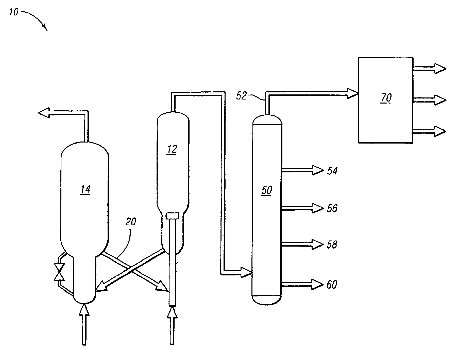
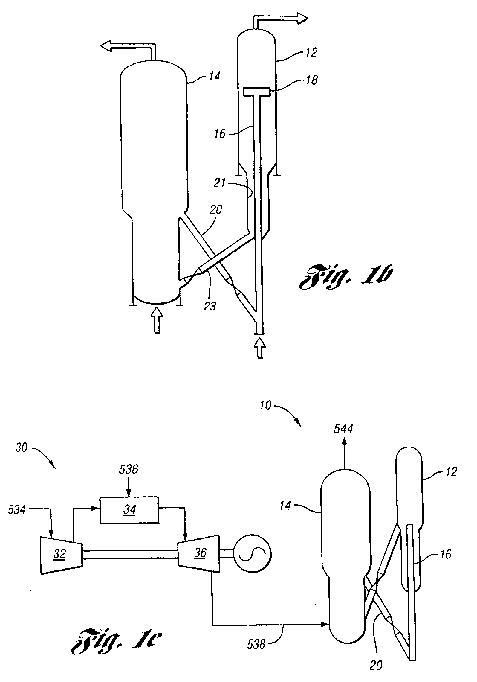
[0021]Embodiments of the present invention generally provide systems and methods of reducing carbon dioxide emissions in a fluid catalytic cracking (FCC) unit having a reactor and a regenerator at gasification conditions. In one example, this is accomplished by using a gas turbine to preheat a feed gas to a regenerator of the FCC unit. As the feed gas is introduced to the regenerator, the heat of the feed gas may be used to burn coke off spent catalyst from the reactor of the FCC unit. This achieves a greater concentration of carbon monoxide, thereby lessening the concentration of carbon dioxide emissions.

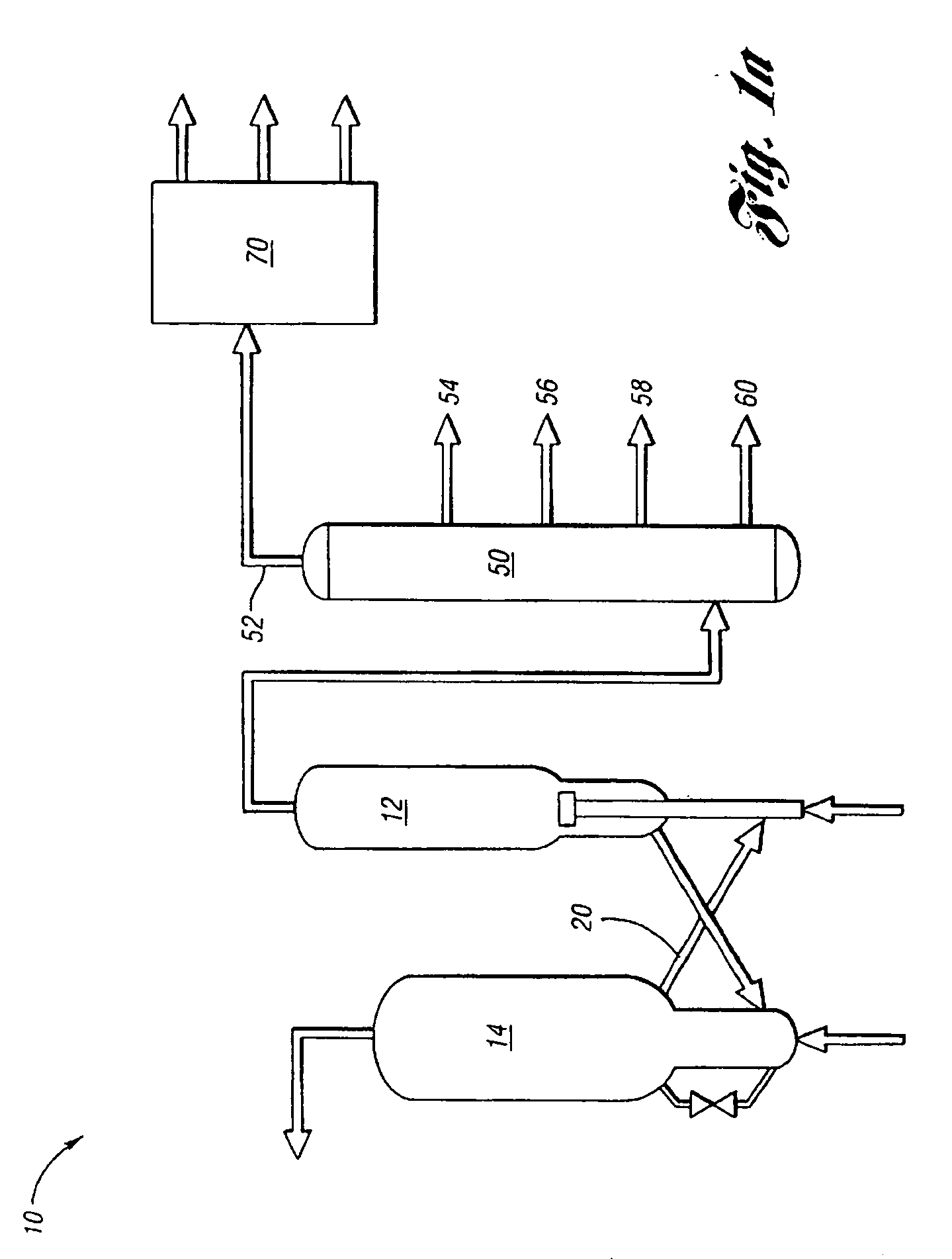
[0022]FIG. 1a illustrates a fluid catalytic cracking (FCC) unit and separation system 10. As shown, the FCC unit 10 comprises a reactor 12 that is configured to receive a hydrocarbon feedstock (fresh feed) and a regenerator 14 in fluid communication with the reactor 12 to receive spent catalyst. The reactor 12 cracks the feedstock therein to an effluent containing hydrocarbons rang...


PUM

PropertyMeasurementUnit
Temperatureaaaaaaaaaa
Pressureaaaaaaaaaa
Pressureaaaaaaaaaa

Abstract

Systems and methods of reducing carbon dioxide emissions in a fluid catalytic cracking unit having a reactor and a regenerator at gasification conditions are disclosed. In one example, a method comprises compressing a first gas at an inlet pressure to a predetermined high pressure to define a compressed gas and combusting a second gas with the compressed gas to a predetermined temperature to define a heated gas. The method further comprises expanding the heated gas to a predetermined low pressure to define a feed gas. The method further comprises introducing the feed gas to the regenerator. The feed gas, now at an elevated temperature, provides heat to the regenerator to burn coke off spent catalyst from the reactor, achieving a proportion of carbon monoxide in a flue gas. In turn, this reduces the concentration of carbon dioxide in the flue gas.

Description

[0001]This application is the result of a joint research agreement between UOP, LLC and BP America, Inc.BACKGROUND OF THE INVENTION[0002]The present invention relates to systems and methods of reducing carbon dioxide emissions in a fluid catalytic cracking unit.[0003]The fluidized catalytic cracking of hydrocarbons is the mainstay process for the production of gasoline and light hydrocarbon products from heavy hydrocarbon charge stocks such as vacuum gas oils or residual feeds. Large hydrocarbon molecules associated with the heavy hydrocarbon feed are cracked to break the large hydrocarbon chains thereby producing lighter hydrocarbons. These lighter hydrocarbons are recovered as product and can be used directly or further processed to raise the octane barrel yield relative to the heavy hydrocarbon feed.[0004]The basic equipment or apparatus for the fluidized catalytic cracking of hydrocarbons has been in existence since the early 1940's. The basic components of the FCC process inclu...

Claims


Application Information

Patent Timeline
IPC IPC(8): B01J8/00
CPCC10G11/185C10G11/182Y02P30/40
Inventor TOWLER, GAVIN P.RUNDELL, DOUGLAS N.
Owner BP CORP NORTH AMERICA INC
Why Eureka
Try Eureka