
Hydrogen storage alloy, hydrogen separation membrane, hydrogen storage tank, and hydrogen absorption and desorption method

a technology of hydrogen storage alloy and hydrogen storage tank, which is applied in the field of hydrogen storage alloy, hydrogen separation membrane, hydrogen storage tank, and hydrogen absorption and desorption method, which can solve the problems of limited further improvement of capacity and very low hydrogen releasing speed

Inactive Publication Date: 2008-07-03
KK TOSHIBA
View PDF2 Cites 20 Cited by
  • Summary
  • Abstract
  • Description
  • Claims
  • Application Information

AI Technical Summary

Benefits of technology

The present invention relates to a hydrogen storage alloy and a method for absorbing and desorbing hydrogen gas using the alloy. The alloy has a specific composition and mole ratios that allow it to absorb and desorb hydrogen gas at specific pressure and temperature conditions. The technical effect of this invention is to provide a reliable and efficient material for storing and utilizing hydrogen gas, which can be used in various applications such as fuel cells and hydrogen vehicles.

Problems solved by technology

Although practically used as a material for batteries, the above-mentioned alloy system type 1) has a discharge capacity of 80% or higher of the theoretical capacity and is thus limited in the further improvement of the capacity.
However, for example, it is pointed out that a La1-xMgxNi2 type alloy among these alloys has a problem of a very low hydrogen releasing speed due to high stability of the alloy with hydrogen.

Method used


Image

  • Hydrogen storage alloy, hydrogen separation membrane, hydrogen storage tank, and hydrogen absorption and desorption method
  • Hydrogen storage alloy, hydrogen separation membrane, hydrogen storage tank, and hydrogen absorption and desorption method
  • Hydrogen storage alloy, hydrogen separation membrane, hydrogen storage tank, and hydrogen absorption and desorption method

Examples


first embodiment

Hydrogen Storage Alloy

[0025]A hydrogen storage alloy according to the invention has a composition defined by the following formula (1).

(Ca1-XLX)(Li1-Y-ZMYNiZ)m  (1)

[0026]In the above formula (1), the component L denotes one or more elements selected from the group consisting of Na, K, Rb, Cs, Mg, Sr, Ba, Sc, Ti, Zr, Hf, V, Nb, Ta, La, Ce, Pr, Nd, Pm, Sm, Eu, Gd, Tb, Dy, Ho, Er, Tm, Yb, and Lu. The component M denotes one or more elements selected from the group consisting of Cr, Mo, W, Mn, Fe, Ru, Co, Ir, Ni, Pd, Pt, Cu, Ag, Au, Zn, Cd, B, Al, Ga, In, Si, Ge, Sn, Pb, Sb, Bi, and S.

[0027]The mole ratios X, Y, Z, and m respectively satisfy the following: 0<X≦0.4, 0≦Y≦0.4, 0.1≦Z≦0.4, and 1.8≦m≦2.2. The reason why the substitution ratio X of the component L is defined as 0<X≦0.4 is because if the substitution ratio X exceeds 0.4, the alloy decomposition occurs to considerably lower the hydrogen desorption capacity. The range of the substitution ratio X is more preferably 0.1≦X≦0.3. It i...

second embodiment

Hydrogen Separation Membrane

[0045]The hydrogen storage alloy according to the first embodiment can be formed in a film-like shape by heat press process. The film-like hydrogen storage alloy functions as a hydrogen separation membrane having hydrogen absorption and desorption properties.

[0046]The hydrogen separation membrane may contain an alloy other than the hydrogen storage alloy. It is desirable that the hydrogen storage alloy is contained at a ratio of 70% by volume or more in the hydrogen separation membrane. This is because if the ratio of the hydrogen storage alloy is lower than 70% by volume, a large quantity of foreign phases is precipitated and the capability as the hydrogen storage material is deteriorated.

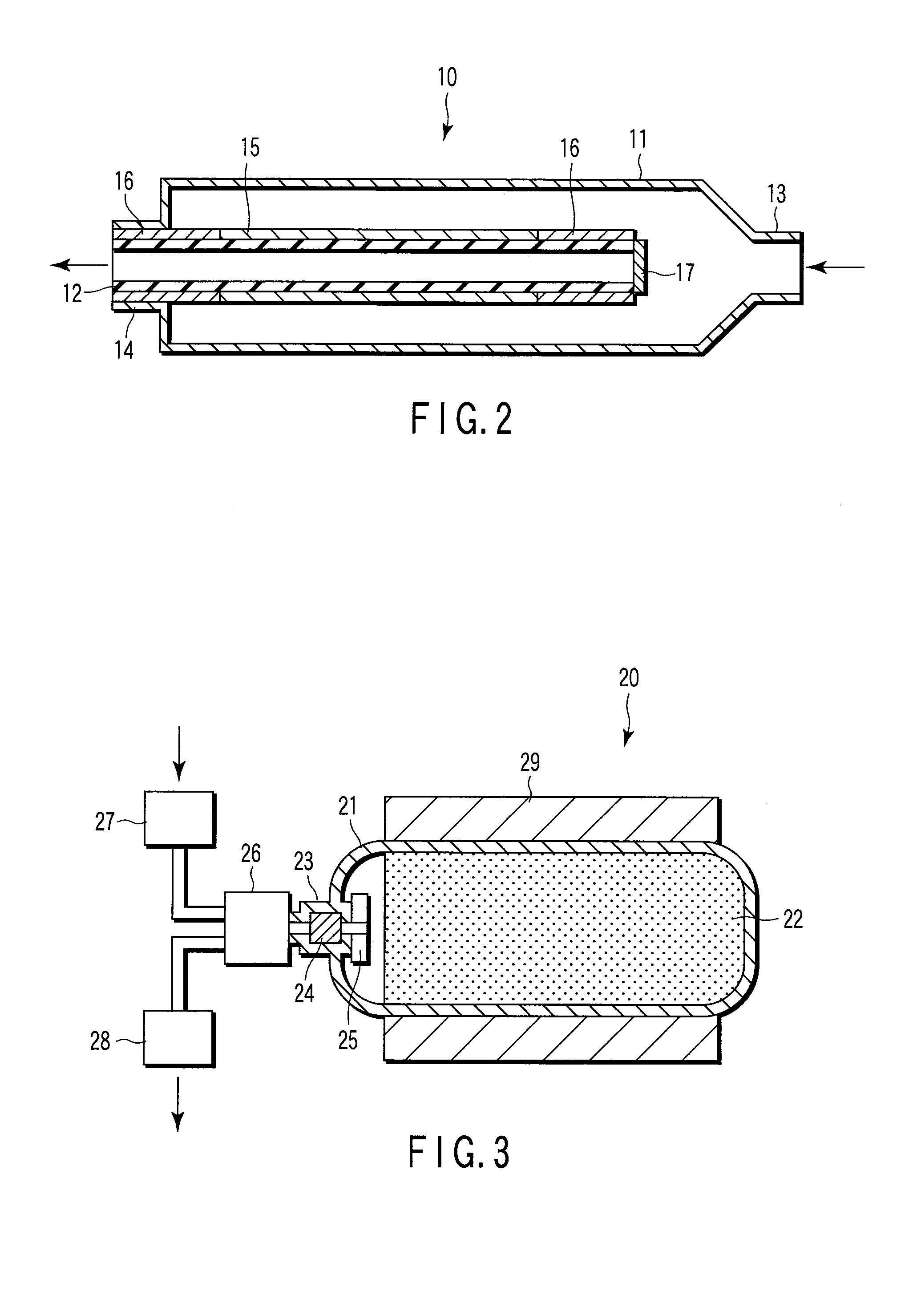
[0047]Next, a hydrogen separation apparatus equipped with the hydrogen separation membrane according to the second embodiment will be described with reference to FIG. 2.

[0048]A hydrogen separation apparatus 10 includes a high pressure tube 11 and a low pressure tube 12....

third embodiment

Hydrogen Storage Tank

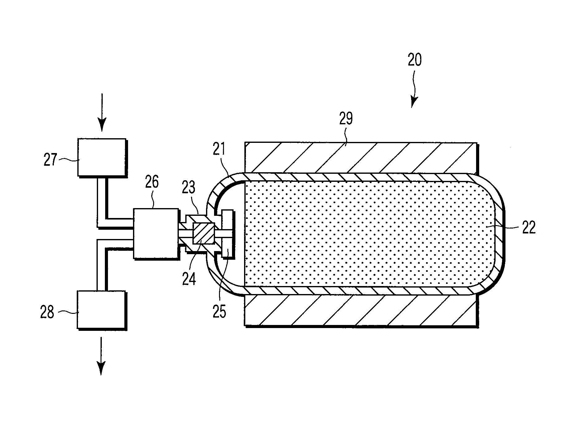
[0052]As shown in FIG. 3, a hydrogen storage tank 20 according to a third embodiment includes a pressure vessel 21 and a hydrogen storage alloy powder 22. The hydrogen storage alloy powder 22 is packed and sealed in the inside of the pressure vessel 21. A powder obtained by crushing and finely pulverizing the hydrogen storage alloy of the first embodiment is used as the hydrogen storage alloy powder 22. The average particle diameter of the hydrogen storage alloy powder 22 is adjusted to be 20 μm. The pressure vessel 21 has an inlet 23 for hydrogen gas and the inlet 23 is equipped with a tank valve 24. Such a hydrogen storage tank 20 can be employed while being incorporated into a hydrogen storage system to be built in, for example, a vehicle.

[0053]The tank valve 24 is installed in one end side of the pressure vessel 21 and a filter 25 is attached to the tank valve 24. The filter 25 is for preventing the hydrogen storage alloy powder 22 from being discharged to t...


PUM

PropertyMeasurementUnit
mole ratioaaaaaaaaaa
temperatureaaaaaaaaaa

Abstract

A hydrogen storage alloy includes a composition defined by the following formula (Ca1-XLX)(Li1-Y-ZMYNiZ)m, wherein the L denotes one or more elements selected from the group consisting of Na, K, Rb, Cs, Mg, Sr, Ba, Sc, Ti, Zr, Hf, V, Nb, Ta, La, Ce, Pr, Nd, Pm, Sm, Eu, Gd, Tb, Dy, Ho, Er, Tm, Yb, and Lu, the M denotes one or more elements selected from the group consisting of Cr, Mo, W, Mn, Fe, Ru, Co, Ir, Ni, Pd, Pt, Cu, Ag, Au, Zn, Cd, B, Al, Ga, In, Si, Ge, Sn, Pb, Sb, Bi, and S, and the mole ratios X, Y, Z, and m respectively satisfy the following 0<X≦0.4, 0≦Y≦0.4, 0.1≦Z≦0.4, and 1.8≦m≦2.2.

Description

CROSS-REFERENCE TO RELATED APPLICATIONS[0001]This application is based upon and claims the benefit of priority from prior Japanese Patent Application No. 2006-267982, filed Sep. 29, 2006, the entire contents of which are incorporated herein by reference.BACKGROUND OF THE INVENTION[0002]1. Field of the Invention[0003]The present invention relates to a hydrogen storage alloy, a hydrogen separation membrane, a hydrogen storage tank, and a hydrogen absorption and desorption method to be used for storing, transporting, and separating hydrogen.[0004]2. Description of the Related Art[0005]A hydrogen storage alloy is an alloy capable of safely and easily storing hydrogen as an energy source and has been highly expected as a new energy conversion and storage material. The application fields of the hydrogen storage alloy as an innovative functional material are wide in a range such as storage and transportation of hydrogen, storage and transportation of heat, heat-mechanical energy conversion...

Claims


Application Information

Patent Timeline
Patent Type & Authority Applications(United States)
IPC IPC(8): B65B31/02C22C30/00B01D71/02B65D85/00
CPCC22C30/06Y10S420/90Y02E60/321B01D53/228B01D67/0041B01D71/022C22C1/0433C22C19/007C22C19/03C22C30/00C22C30/02C22C30/04B01D67/0074B01D2325/02F17C11/005Y02E60/32
Inventor KOHNO, TATSUOKI
Owner KK TOSHIBA
Learn More