Ultrasonic transducer system

a transducer and ultrasonic technology, applied in ultrasonic/sonic/infrasonic diagnostics, instruments, tomography, etc., can solve the problems of increasing the cost and complexity of their respective ultrasonic imaging systems, unfavorable side lobes in the amplitude distribution, and reducing image quality, so as to improve the acoustic wave characteristics

Active Publication Date: 2008-07-03
SOUND TECH
View PDF31 Cites 39 Cited by
  • Summary
  • Abstract
  • Description
  • Claims
  • Application Information

AI Technical Summary

Benefits of technology

[0007]In view of the foregoing, an object of the present invention is to provide an improved ultrasound transducer system that is operable to yield improv

Problems solved by technology

However, this typically results in the creation of undesirable side lobes in the amplitude distribution at the focal point of the acoustic lens.
These side

Method used


Image

  • Ultrasonic transducer system
  • Ultrasonic transducer system
  • Ultrasonic transducer system

Examples


Embodiment Construction

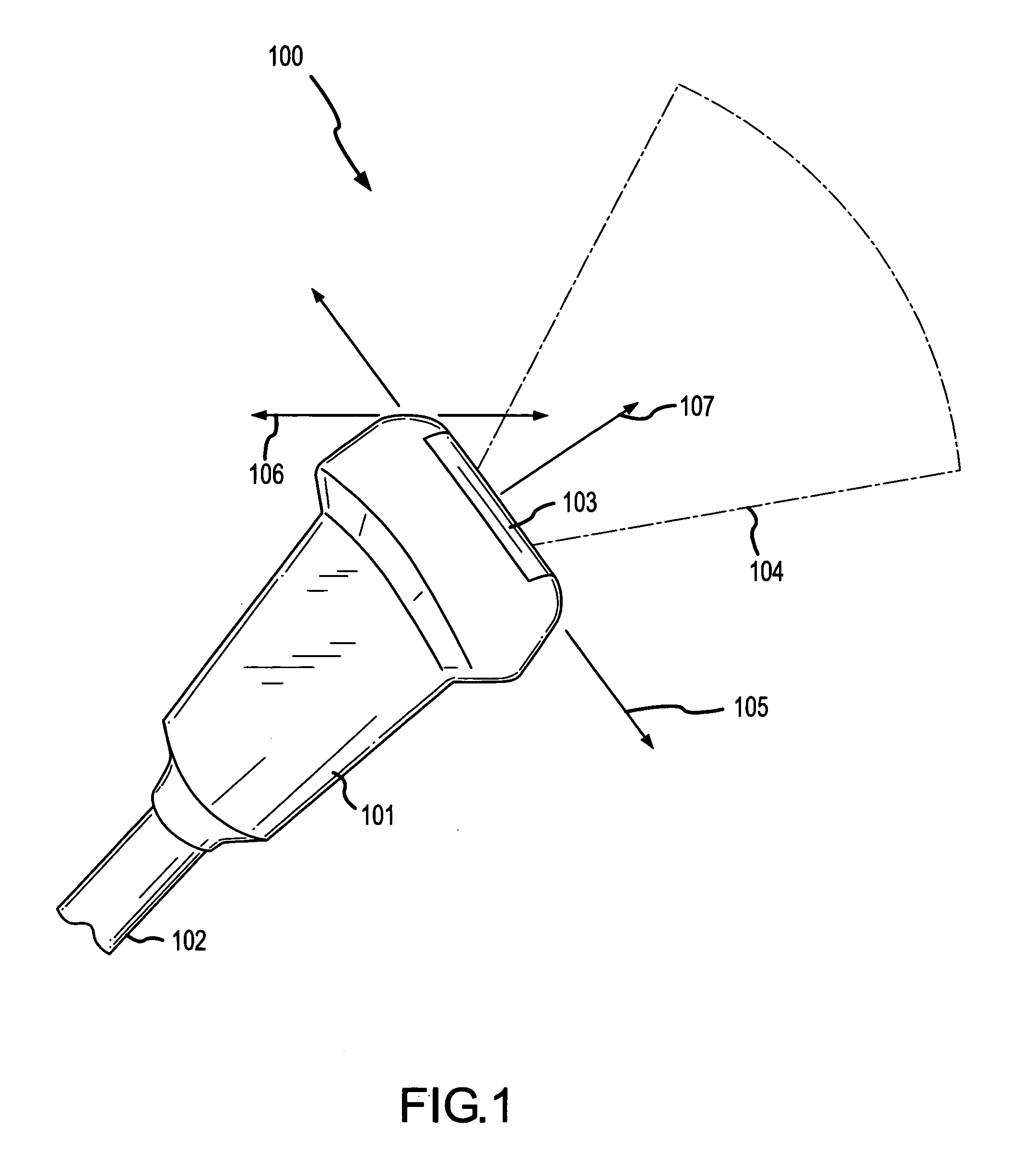
[0050]FIG. 1 illustrates a perspective view of an ultrasound transducer probe assembly 100.

[0051]The probe assembly 100 includes a housing 101 and a cable 102. The cable 102 is interconnected to an ultrasound imaging apparatus (not shown). Generally, the probe assembly 100 includes a plurality of ultrasonic transducers contained within the housing 101 and operable to transmit ultrasonic energy through a probe assembly face 103 along one end of the probe assembly 101. The ultrasonic energy, in the form of acoustic waves, may be directed through the outer surface of a patient and into the internal structure of the patient. The acoustic waves may interact with and reflect off of various internal features. These reflections may then be detected by the probe assembly 100 and displayed as images of the internal structure of the patient by the ultrasound imaging apparatus.

[0052]Various parameters of the probe assembly 100 may differ from that shown in the probe assembly 100 of FIG. 1. As s...


PUM


Abstract

An improved acoustic lens and an improved ultrasonic transducer system comprising an improved acoustic lens and related methods are provided. The improved acoustic lens may have a uniform loss along an elevation axis or may have a loss along the elevation axis that provides for an apodization of an acoustic signal. The improved acoustic lens may be a multi-component lens. In a two-component lens embodiment, the inner lens component, for interfacing with a transducer, may have a concave outer surface and the outer lens component may have a flat or convex outer surface. In a three-component lens embodiment, the inner lens component, for interfacing with a transducer, may have a concave outer surface, the middle lens component may have a concave outer surface and the outer lens component may have a flat or convex outer surface.

Description

RELATED APPLICATIONS [0001]This application claims priority from U.S. Provisional Patent Application Ser. No. 60 / 862,757, filed Oct. 24, 2006, entitled “Improved Ultrasonic Transducer System,” and the entire disclosure of which is incorporated by reference in its entirety herein.FIELD OF THE INVENTION [0002]The present invention relates to ultrasound imaging probes, and more particularly to improved ultrasonic transducer systems and related methods.BACKGROUND OF THE INVENTION [0003]Ultrasound imaging probes continue to enjoy widespread use in the medical field. By way of example, ultrasound probes are utilized for a wide variety of external, laparoscopic, endoscopic and intravascular imaging applications. The ultrasound images provided by imaging probes may, for example, be used for diagnostic purposes.[0004]Ultrasound imaging probes typically include a plurality of parallel piezoelectric transducer elements arranged along a longitudinal axis, with each element interconnected to a p...

Claims


Application Information

Patent Timeline
IPC IPC(8): G10K11/00
CPCG10K11/30
Inventor DIETZ, DENNIS RAYMONDOAKLEY, CLYDE GERALDMORGAN, DUANEPATWA, DAIDIPYA
Owner SOUND TECH
Why Eureka
Try Eureka