Methods and systems for determining mud flow velocity from measurement of an amplitude of an artificially induced radiation

a technology of amplitude and measurement method, applied in the direction of instruments, survey, borehole/well accessories, etc., can solve the problems of difficult inference of fluid volume and rate, substantial loss of fluid into the formation,

Inactive Publication Date: 2008-07-03
SCHLUMBERGER TECH CORP
View PDF5 Cites 33 Cited by
  • Summary
  • Abstract
  • Description
  • Claims
  • Application Information

AI Technical Summary

Problems solved by technology

Modern oil and gas explorations typically use LWD or MWD tools, instead of wireline tools, for formation logging due to the saving in time and costs.
The higher hydraulic pressure of the drilling fluids may result in a substantial loss of fluid into the formation when a permeable and low pressure zone of the earth formation is encountered.
However, inference of the fluid volumes and rates observed is difficult due to the lack of a direct flow rate measurement in the annulus.

Method used


Image

  • Methods and systems for determining mud flow velocity from measurement of an amplitude of an artificially induced radiation
  • Methods and systems for determining mud flow velocity from measurement of an amplitude of an artificially induced radiation
  • Methods and systems for determining mud flow velocity from measurement of an amplitude of an artificially induced radiation

Examples


first embodiment

[0026]FIG. 3 shows a flow chart in accordance with the present invention. In step 101, the PNG is operating and oxygen contained in the mud is being activated as it passes the PNG. In step 102, the amount of gamma ray radiation emitted by the decay of activated oxygen is measured by two detectors above the PNG. In step 103, a processing unit, such as the processor 21 in FIG. 2, may be used to take the natural logarithm of the ratio of the two numbers, and in step 104 this number may be divided by the decay constant of activated oxygen to obtain the travel time for the mud to pass between the two detectors. One of ordinary skill in the art may appreciate that instead of using a logarithm based on the number e other based logarithms may be used in embodiments of the present invention and combined with a different constant of proportionality to obtain the travel time. Merely by way of example, if the base of the logarithm is 2, then the logarithm of the ratio of the amplitudes must be ...

second embodiment

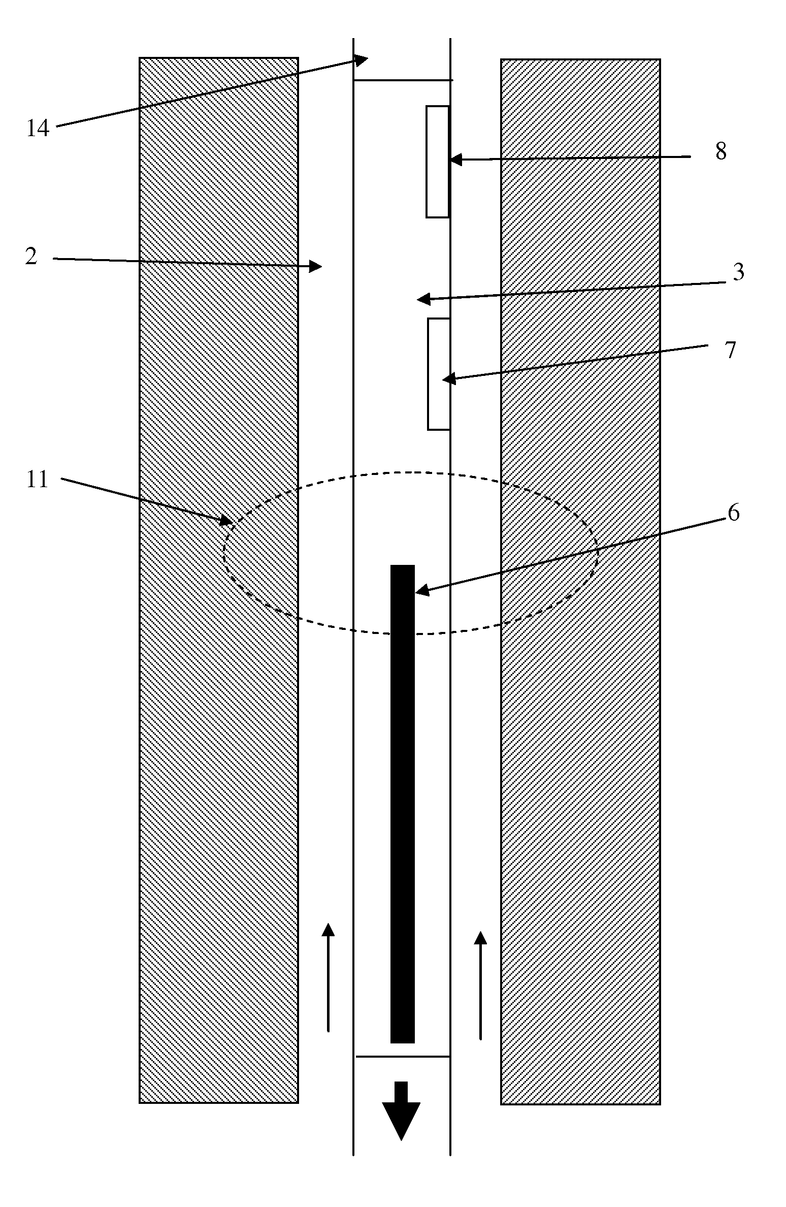
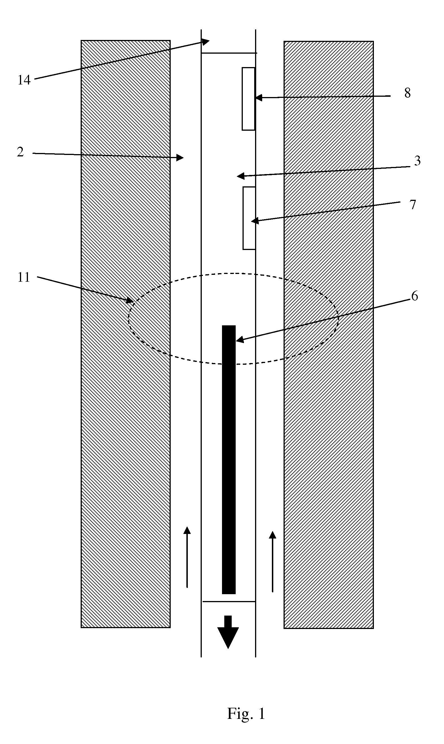
[0027]In the present invention, illustrated in FIG. 4, only one gamma ray detector 7 is employed, together with a second means 15 of determining the mud flow velocity at particular times. In FIG. 3 the flow measurement may be a turbine-based flow rate measurement. As illustrated, the mud flows through the drillstem in a channel 16, which drives the turbine 15, the voltage from which can be used to derive a flow rate. Other means of determining the mud flow velocity at particular times include using the PNG to directly determine time-of-flight, by inference from the rate at which mud is being pumped into the well at the surface and / or the like.

[0028]At a time when the mud flow velocity may be determined using means 15, the gamma ray amplitude may be measured at the detector 7. From the known mud flow velocity, the time required for the mud to traverse the distance between the PNG and the detector may be calculated. The gamma ray amplitude may be measured at detector 7 at times when t...


PUM


Abstract

Embodiments of the present invention relate in general to methods and apparatus for determining downhole mud flow rates and other downhole parameters. More specifically, but not by way of limitation, an embodiment of the present invention may provide a method for determining a downhole parameter that includes operating a pulsed neutron generator, detecting the activated drilling fluid at-least one known distance (d) from the pulsed neutron generator, and determining a time-of-flight (t) for the activated drilling fluid slug to travel from the pulsed neutron generator to a detection point, or between detection points

Description

CROSS-REFERENCE TO RELATED APPLICATIONS[0001]This application claims the benefits of priority from Application Number 0625904.8, entitled “METHODS AND SYSTEMS FOR DETERMINING MUD FLOW VELOCITY FROM MEASUREMENT OF AN AMPLITUDE OF AN ARTIFICIALLY INDUCED RADIATION,” filed in the United Kingdom on Dec. 23, 2006, which is commonly assigned to assignee of the present invention and hereby incorporated by reference in its entirety.BACKGROUND[0002]When drilling a borehole through a geologic formation, it is important to know the downhole conditions to ensure that the drill bit is operating correctly. These conditions include, among other things, the diameter of the borehole and, therefore, the volume of the drilling fluid at any given point. In addition, the formation properties may be measured to predict the presence of oil or gas. Formation properties may be logged with wireline tools, logging while drilling (“LWD”) tools, or measurement while drilling (“MWD”) tools. Modern oil and gas ex...

Claims


Application Information

Patent Timeline
Patent Type & Authority Applications(United States)
IPC IPC(8): G01V5/14G01V5/00E21B21/08E21B47/10
CPCE21B47/1015E21B47/11E21B47/111
Inventor JEFFRYES, BENJAMIN
Owner SCHLUMBERGER TECH CORP
Why Eureka
Try Eureka