
Firing jig assembling apparatus, firing jig disassembling apparatus, circulating apparatus, method for firing ceramic molded body, and method for manufacturing honeycomb structure

a technology of assembling apparatus and circulating apparatus, which is applied in the direction of lighting and heating apparatus, charging devices, furnaces, etc., can solve the problems of contamination of the environment and human body, and the problem of serious problems

Inactive Publication Date: 2008-07-03
IBIDEN CO LTD
View PDF99 Cites 79 Cited by
  • Summary
  • Abstract
  • Description
  • Claims
  • Application Information

AI Technical Summary

Benefits of technology

The present invention relates to a firing jig assembling apparatus and a firing jig disassembling apparatus for ceramic molded bodies. The apparatuses include a robot arm and a table or conveyor for placing a firing jig with a ceramic molded body being mounted thereon. The apparatuses also include a lid member attachment mechanism for attaching a lid member to the firing jig. The apparatuses can pile up multiple firing jigs and have a jig taking-out mechanism for removing and using the lid member attachment mechanism. The apparatuses can also have a conveyor that moves intermittently and a jig receiving mechanism for receiving the firing jig from the firing furnace. The invention allows for efficient and automated assembly and disassembly of firing jigs for ceramic molded bodies.

Problems solved by technology

In recent years, particulates such as soot contained in exhaust gases that are discharged from internal combustion engines of vehicles, such as buses and trucks, and construction machines, have raised serious problems as contaminants harmful to the environment and the human body.

Method used


Image

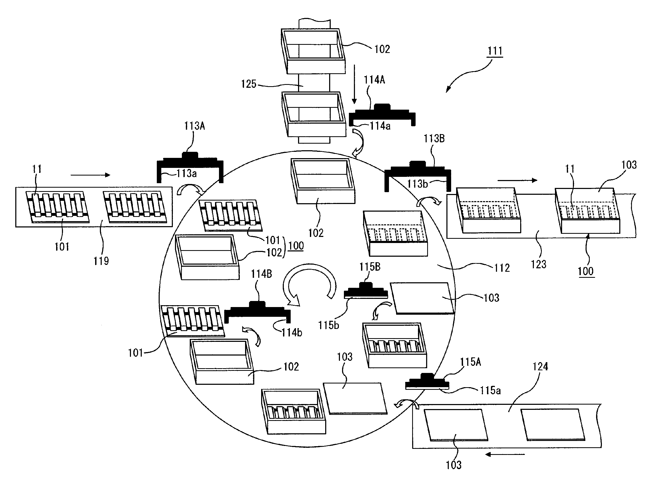
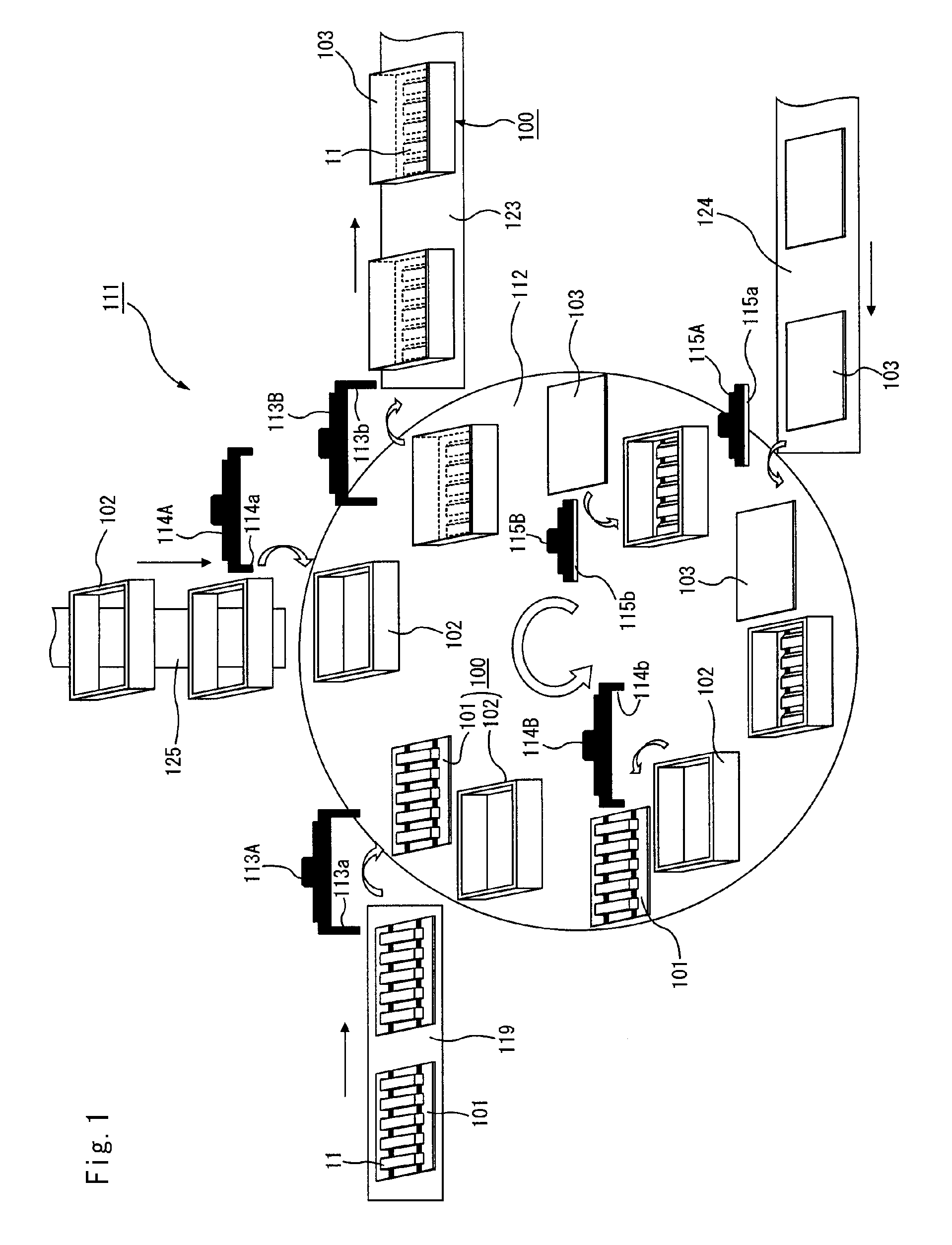
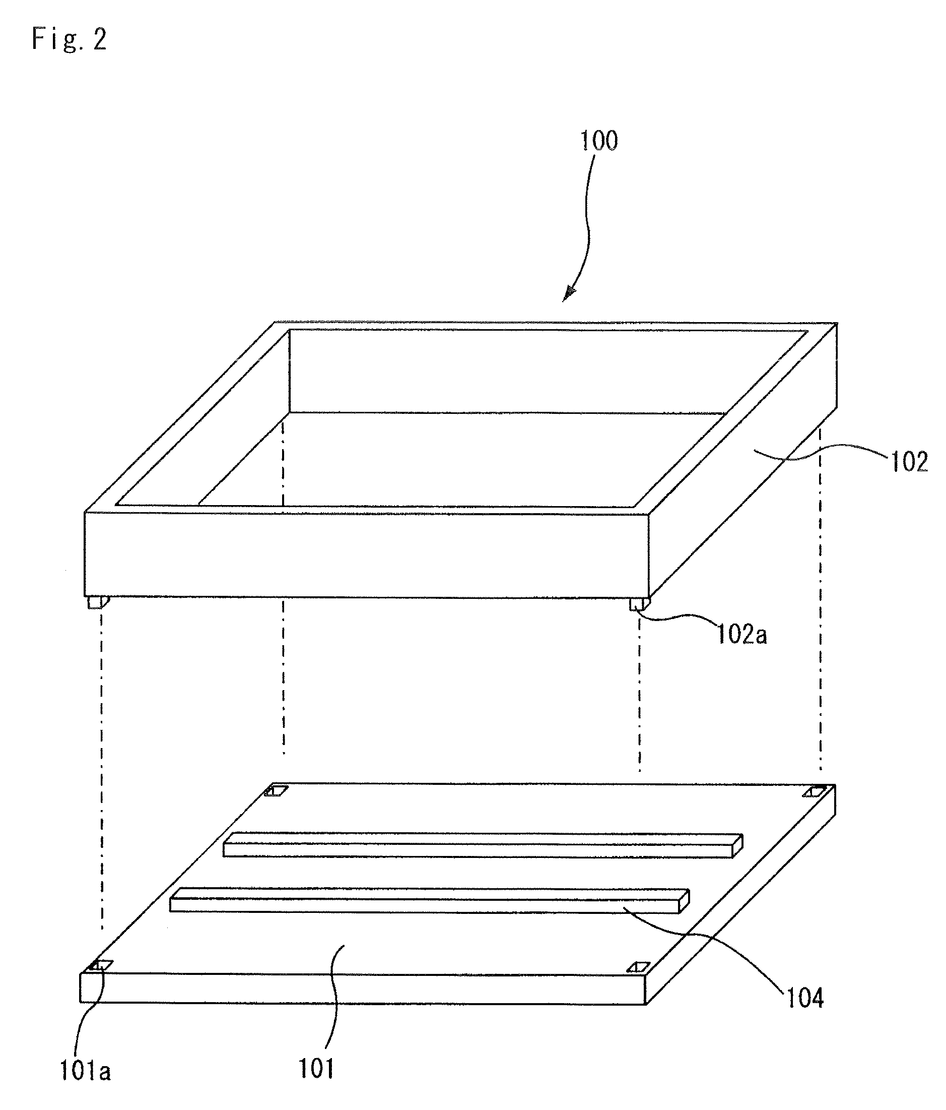
  • Firing jig assembling apparatus, firing jig disassembling apparatus, circulating apparatus, method for firing ceramic molded body, and method for manufacturing honeycomb structure
  • Firing jig assembling apparatus, firing jig disassembling apparatus, circulating apparatus, method for firing ceramic molded body, and method for manufacturing honeycomb structure
  • Firing jig assembling apparatus, firing jig disassembling apparatus, circulating apparatus, method for firing ceramic molded body, and method for manufacturing honeycomb structure

Examples


example 1

[0363]Powder of α-type silicon carbide having an average particle size of 10 μm (250 kg), powder of α-type silicon carbide having an average particle size of 0.5 μm (100 kg) and an organic binder (methyl cellulose) (20 kg) were mixed to prepare a mixed powder.

[0364]Next, separately, a lubricant (UNILUB, made by NOF Corp.) (12 kg), a plasticizer (glycerin) (5 kg) and water (65 kg) were mixed to prepare a liquid mixture, and this liquid mixture and the mixed powder were mixed by using a wet-mixing machine so that a wet mixture was prepared.

[0365]Next, this wet mixture was transported to an extrusion-molding machine by using a transporting apparatus, and charged into a material charging port of the extrusion-molding machine.

[0366]The wet mixture was then extrusion-molded into a molded body having the same shape as shown in FIG. 12A except that ends of the cells had not been plugged.

[0367]Next, the honeycomb molded body was dried by using a drying apparatus in which microwaves and hot a...


PUM


Abstract

A circulating apparatus includes a firing jig assembling apparatus, a firing furnace, a firing jig disassembling apparatus, and a transporting conveyor. The firing jig assembling apparatus includes a lid member attaching mechanism that attaches the lid member to a predetermined position of the firing jig placed on the table or the conveyor; and a jig delivering mechanism that delivers the firing jig which has the ceramic molded body being mounted thereon and the lid member being attached thereto, to the firing furnace. The firing jig disassembling apparatus further includes a jig receiving mechanism that receives the firing jig which has the fired ceramic molded body being mounted thereon and the lid member being attached thereto, from the firing furnace; and a lid member detaching mechanism that detaches the lid member from the firing jig placed on the table or the conveyor with the lid member being attached thereto.

Description

CROSS-REFERENCE TO RELATED APPLICATIONS[0001]This application is a continuation application of PCT / JP2006 / 309117 filed on May 1, 2006. The contents of this application are incorporated herein by reference in their entirety.BACKGROUND OF THE INVENTION[0002]1. Field of the Invention[0003]The present invention relates to a firing jig assembling apparatus, a firing jig disassembling apparatus, a circulating apparatus, a method for firing a ceramic molded body, and a method for manufacturing a honeycomb structure.[0004]2. Discussion of the Background[0005]In recent years, particulates such as soot contained in exhaust gases that are discharged from internal combustion engines of vehicles, such as buses and trucks, and construction machines, have raised serious problems as contaminants harmful to the environment and the human body.[0006]Various honeycomb filters using honeycomb structural bodies as filters that collect particulates in exhaust gases to purify the exhaust gases have been pr...

Claims


Application Information

Patent Timeline
Patent Type & Authority Applications(United States)
IPC IPC(8): B28B1/02B29C65/10
CPCF26B25/003Y10T156/1105Y10T156/1906F27D3/12
Inventor KAWAI, TSUYOSHISAIJO, TAKAMITSUKASAI, KENICHIRO
Owner IBIDEN CO LTD
Learn More