Organic el light-emitting apparatus and method of manufacturing the same

a light-emitting apparatus and organic technology, applied in the manufacture of electrode systems, electric discharge tubes/lamps, discharge tubes luminescent screens, etc., can solve the problems of incomparable reduction of electric resistivity, non-uniformity (luminance gradient) of luminous brightness, and reduced brightness, so as to achieve high electric resistivity and reduce luminance gradient occurrence, the effect of uneven brightness

Inactive Publication Date: 2008-07-03
YAMAGATA PROMOTIONAL ORG FOR INDAL TECH
View PDF10 Cites 21 Cited by
  • Summary
  • Abstract
  • Description
  • Claims
  • Application Information

AI Technical Summary

Benefits of technology

[0022]According to the organic EL light-emitting apparatus having the above-mentioned configuration, the main electric power supply point and the auxiliary electric power supply point through the sealing member are formed for at least one of the first electrode and the second electrode between which the organic light-emitting functional layer is sandwiched. Therefore, the high electric resistivity of the material constituting the first electrode or the second electrode is compensated, whereby the occurrence of the luminance gradient can be reduced.
[0023]According to the organic EL light-emitting apparatus having the above-mentioned configuration, electric power is fed to the transparent electrode from the sealing member through the conductive columnar members interspersedly formed on the transparent electrode serving as the first electrode in the plane direction of the substrate. Therefore, it can effectively be prevented that the brightness unevenness is produced due to the high electric resistivity of the material, represented by, e.g., ITO, for the transparent electrode. Accordingly, when the organic EL element is used for a surface light-emitting source having relatively large area, the luminance gradient in which the brightness is reduced as the element i

Problems solved by technology

Therefore, when the EL element is used as a surface light-emitting source having large area, non-uniformity (luminance gradient) is produced on the luminous brightness due to voltage drop of the transparent electrode.
Therefore, the luminous brightness is affected by the voltage drop of the ITO as the element is apart from an electric power supply point to the transparent electrode, which entails a problem that the brightness is reduced as the element is apart from the electric power supply point to the transparent electrode.
In order to overcome the aforesaid problem, materials, having reduced electric resistivity, for the transparent electrode represented by ITO have been proposed, but these proposals do not realize the incompa

Method used


Image

  • Organic el light-emitting apparatus and method of manufacturing the same
  • Organic el light-emitting apparatus and method of manufacturing the same
  • Organic el light-emitting apparatus and method of manufacturing the same

Examples


first embodiment

[0041]An organic EL light-emitting apparatus according to the present invention will be explained with reference to the embodiment shown in the drawings. Firstly, FIGS. 1 to 8 show processes of manufacturing the organic EL light-emitting apparatus according to the

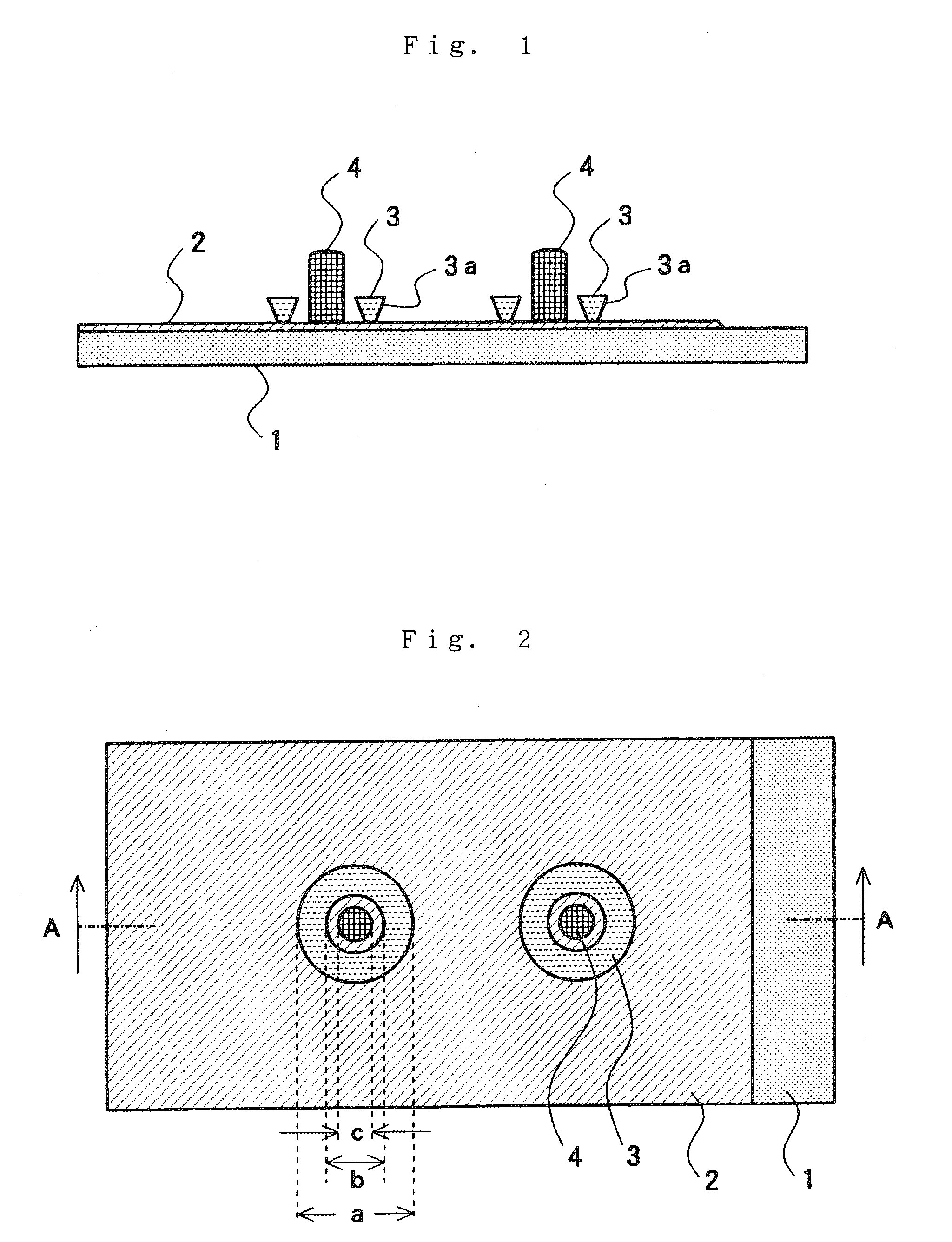
[0042]FIG. 1 is an enlarged sectional view of an essential part of the organic EL light-emitting apparatus at an initial stage of the manufacturing process, and FIG. 2 shows the same essential part viewed from the top. Specifically, FIG. 1 corresponds to the sectional view seen in the direction of an arrow from A-A line in FIG. 2.

[0043]As shown in FIGS. 1 and 2, the organic EL light-emitting apparatus is formed on a substrate 1 made of a transparent or semitransparent material such as a glass or the like or a light-transmitting resinous material. The substrate 1 has a thickness of about 0.1 to 10 mm, which thickness is selected considering the mechanical strength, weight, etc. In general, suitably the thickness of the subst...

second embodiment

[0069]FIG. 10 is an enlarged sectional view of an essential part of the organic EL light-emitting apparatus at an initial stage of the manufacturing process according to the present invention. FIG. 10 corresponds to FIG. 1 explained previously. In FIG. 10, the components having the same function as those shown in FIG. 1 are identified by the same reference numerals, and their detailed explanations are omitted.

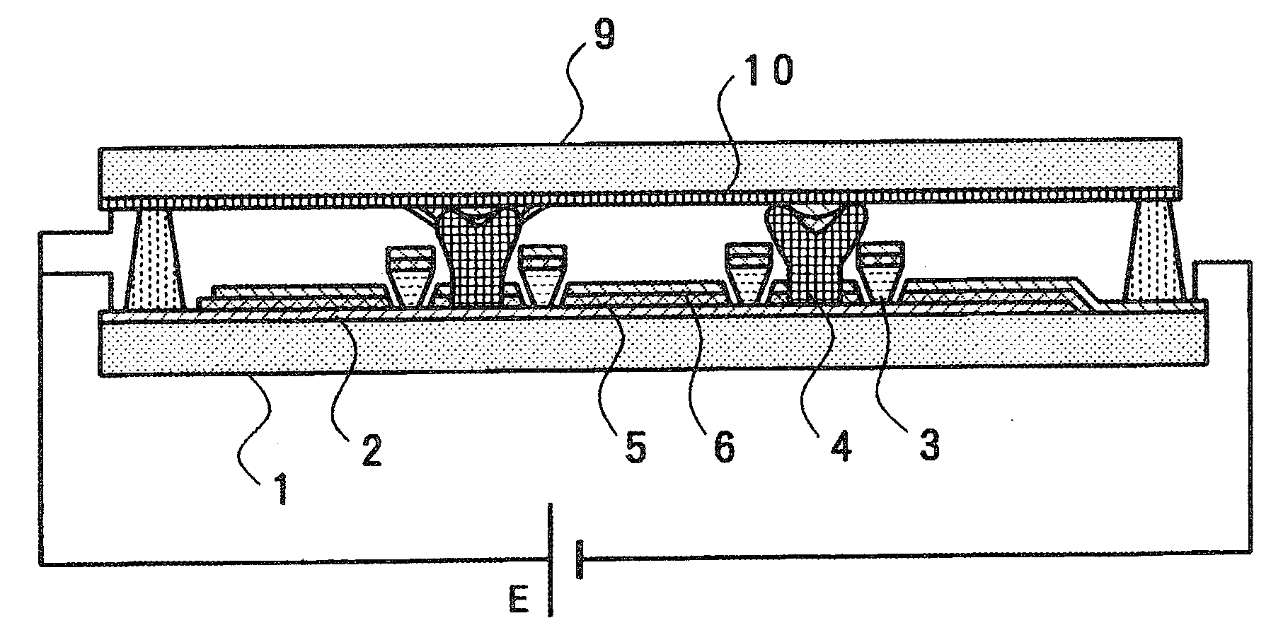
[0070]In the configuration shown in FIG. 10, a gap holding member 11 having hardness higher than that of the conductive material formed at the peripheral portion of the columnar member 4 is accommodated at a core part of the columnar member 4 provided upright on the transparent electrode 2. In case where the columnar member 4 provided with the gap holding member 11 is used, the columnar member 4 functions as a reinforcing member for maintaining a space (gap) between the substrate 1 and the sealing member 9 with the sealing member 9 sealing as shown in FIG. 8.

third embodiment

[0071]FIG. 11 is an enlarged sectional view of an essential part of the organic EL light-emitting apparatus at an initial stage of the manufacturing process according to the present invention. FIG. 11 corresponds to FIG. 1 explained previously. In FIG. 11, the components having the same function as those shown in FIG. 1 are identified by the same reference numerals, and their detailed explanations are omitted.

[0072]In the configuration shown in FIG. 11, a gap holding member 11 is provided upright on the transparent electrode 2 separately from the columnar member 4 provided upright on the transparent electrode 2. When the sealing member 9 seals as shown in FIG. 8 in the configuration in which the gap holding member 11 is provided upright on the transparent electrode 2, the gap holding member 11 functions as a reinforcing member for maintaining a space (gap) between the sealing member 9 and the substrate 1.


PUM


Abstract

The present invention provides an organic EL light-emitting apparatus that can compensate a voltage drop caused on a transparent electrode and that can prevent the occurrence of brightness unevenness caused by the voltage drop.
A transparent electrode 2, an organic light-emitting functional layer 5, and a back electrode 6 are successively laminated on a light-transmitting substrate 1, and a sealing member 9 for sealing the transparent electrode, the organic light-emitting functional layer, and the back electrode is provided so as to accommodate them between the substrate 1 and the sealing member 9. A conductive layer 10 is formed on the sealing member 9, and conductive columnar members 4 are interspersedly formed between the conductive layer 10 and the transparent electrode 2 in the plane direction of the substrate 1. Accordingly, electric power is supplied to the transparent electrode 2 from the conductive layer 10 through the conductive columnar members 4.

Description

BACKGROUND OF THE INVENTION[0001]1. Field of the Invention[0002]The present invention relates to an organic EL light-emitting apparatus that uses an organic EL (electroluminescence) element as a surface light-emitting source having relatively large area, and a method of manufacturing the same.[0003]2. Description of the Related Art[0004]Since an organic EL element has a high luminous efficiency by being driven with DC low voltage, and can be made light in weight and thin in size, it has been utilized for a flat panel display (FPD) in some portable apparatuses. Further, an apparatus utilizing the organic EL element as a surface light-emitting source, e.g., as a backlight of a liquid crystal display device, has been proposed.[0005]On the other hand, the organic EL element can provide each color of light of R (red), G (green), and B (blue) by selecting a material used for a light-emitting functional layer. Therefore, white color or whitish color can also be obtained by using the afores...

Claims


Application Information

Patent Timeline
IPC IPC(8): H01J1/62H01J9/04
CPCH01L51/5203H01L2251/5361H01L51/524H01L51/5212H10K50/805H10K50/814H10K50/841H05B33/26H05B33/04
Inventor KAJIKAWA, FUJIOSUZUKI, JOJI
Owner YAMAGATA PROMOTIONAL ORG FOR INDAL TECH
Why Eureka
Try Eureka