In many operation scenarios the required pulsed
energy transfer (high average and / or peak power) and subsequent thermal effects may create certain detrimental effects, such as reduction of lamp efficiency, changes in lamp spectral output, reduction of the delivered
radiation due to
fouling of optically transmitting surfaces, damage of lamp components, and reduction of lamp service lifetime.
The heretofore known pulsed power supply topologies and resulting operation methods can be problematic and inadequate for meeting increased requirements of the newest generation of high power pulsed flash lamps.
Furthermore, it is known that the CW mercury lamps (among others) have an inherent problem of performance degradation due to the thermal gradient-induced
fouling (minerals attraction) of lamp cooling jackets.
Unfortunately, such
brute force techniques can result in a corresponding degradation of lamp lifetime and performance consistency.
This is due to the increased average and peak energy loading within the lamp envelope, eventually accelerating the process of materials degradation and failure.
The formation and establishment of
plasma down the
flash lamp bore actually presents a complex, dynamically changing load to the pulsed power supply.
While adherence to this straight-forward and proven method has some advantages, it can also have some limitations in terms of
electrical efficiency and lamp degradation.
Much of this wasted high power
thermal energy becomes one of the dominant contributors to lamp performance degradation.
These existing methods and devices are entirely unsuitable in many high power UV
processing applications, which require very low duty cycles (less than about two percent), very short pulses (microseconds), higher peak power (greater than about 1,000,000 Watts / pulse), and higher average power levels (greater than about 5,000 Watts input).
An additional problem source is the type of simmer mode that has universally been applied to the older generation of
high peak power pulsed flash lamps.
The problem with this method is that at some point of increasing
pulse repetition frequency, the
thermal dissipation effects within the lamp envelope from the combination of this additional simmer power, in addition to the increasing average discharge power, tends to require ever increasing amounts of simmer power input in order to force the post-discharge lamp impedance excursions into a safe, lower impedance region that will prevent
quenching of the arc between pulses.
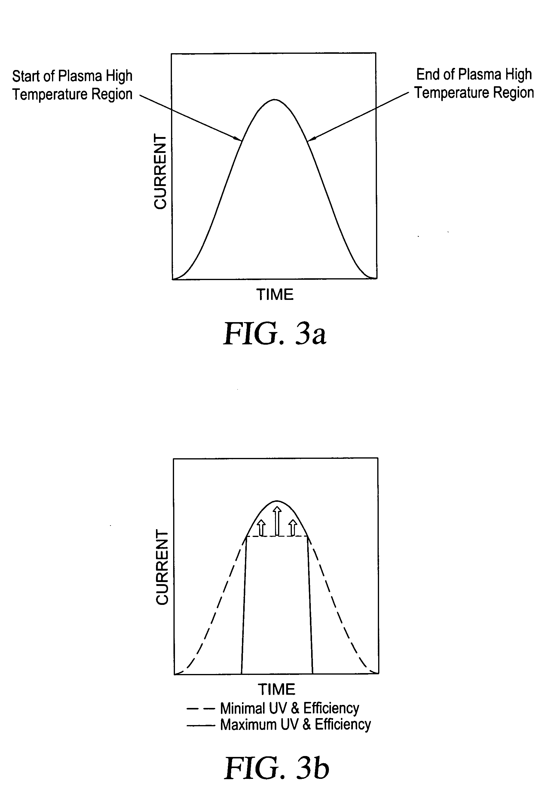
Subsequently, the lamp is no longer operating during the peak of the
current pulse at the lowest impedance (Z0) for which it and the pulsed power supply were designed to operate most efficiently and with integrity of performance In such a process, additional simmer power is expended in order to maintain high power pulsed lamp operation, while at the same time resulting in poorer lamp performance because the lamp is then no longer operating within the Z0 regime for which it was designed.
When applying the legacy simmer mode power techniques (used for the older generation of pulsed discharge lamps) to the new generation of high power pulsed lamps, the resulting performance is less efficient and generally a liability.
Under such conditions a topology that incorporates a continuous and
high current simmer mode is not necessarily the best choice, because the simmer current power expenditure can comprise a much larger portion of the overall
power consumption, thereby lowering overall
electrical efficiency.
Additionally, when applied to
high peak and average power lamps, the various methods utilized for creating a suitable ignition pulse are a bit complicated, fragile, not suited for continuous high repetition rate operation, and tend to be detrimental to lamp
electrode and envelope lifetime if applied very frequently.
Since the
work function of a thermionic dispenser
cathode is partly a function of
cathode temperature, any lamp operation method that allows lower-than-required
cathode temperature excursions is likely to exhibit deleterious effects resulting from a subsequently less efficient charge transfer at the
electrode surface.
This is why the utilization of the so-called “pseudo simmer” technique, which applies an ignition pulse and subsequent simmer current prior to every main discharge pulse, has not been considered useful for high power and
continuous operation (even low-rate)
pulse repetition frequency (PRF) applications.

