Orbital speed reducer by belt

a technology of orbital speed reduction and belt, which is applied in the direction of belt/chain/gearing, friction gearing, mechanical equipment, etc., can solve the problems of transmission torque limitation and possible great speed reduction, and achieve the effect of low production cost, simple structure and low cost mechanism

Inactive Publication Date: 2008-07-03
GRAVIO VALMOR CUNHA
View PDF5 Cites 1 Cited by
  • Summary
  • Abstract
  • Description
  • Claims
  • Application Information

AI Technical Summary

Benefits of technology

[0003]The present invention provides other possibility to use the idea of the planetary gear mechanism in a reduction gear or an overdrive gear, using pulleys instead of toothed gears. The great advantage of this type of pulley reducer or overdrive is the great reduction reached in just one reduction stage besides the very simple structure. For equipments which use low torques, such as toys, the use of gasket o-ring working as a belt in this technique, can make the production cost to be lower than the conventional mechanical reduction. For higher power transmissions, the use of multiple channels belts as “POLI V” belts or tires, for instance, makes possible to have low cost mechanism.

Problems solved by technology

These transmissions make possible great speed reduction however there is the limiting factor, which is the precise aspect of the complicated teeth and the transmitted torque limitation due to the small contact area between the teeth of the gears.

Method used


Image

  • Orbital speed reducer by belt
  • Orbital speed reducer by belt
  • Orbital speed reducer by belt

Examples


Embodiment Construction

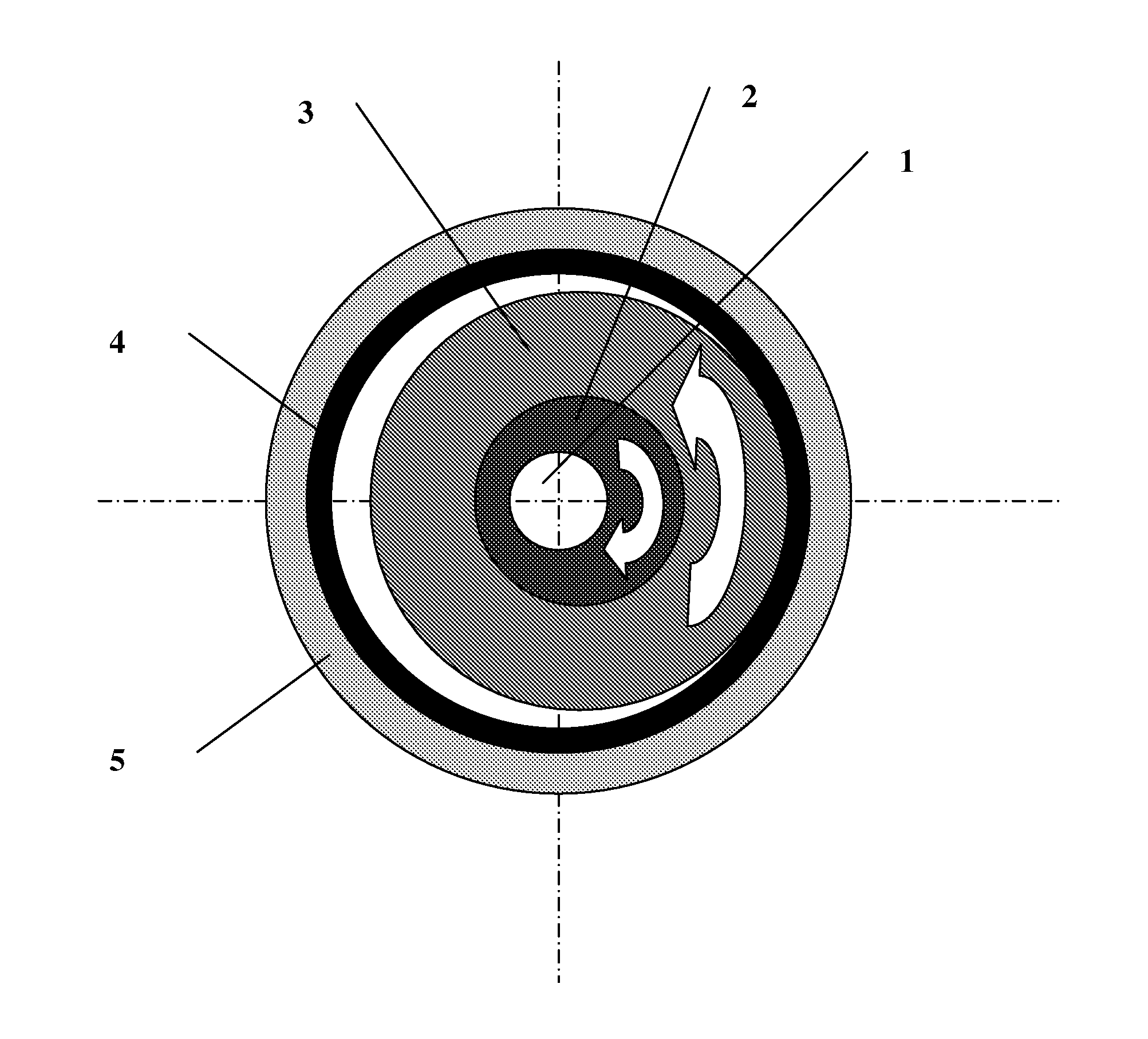
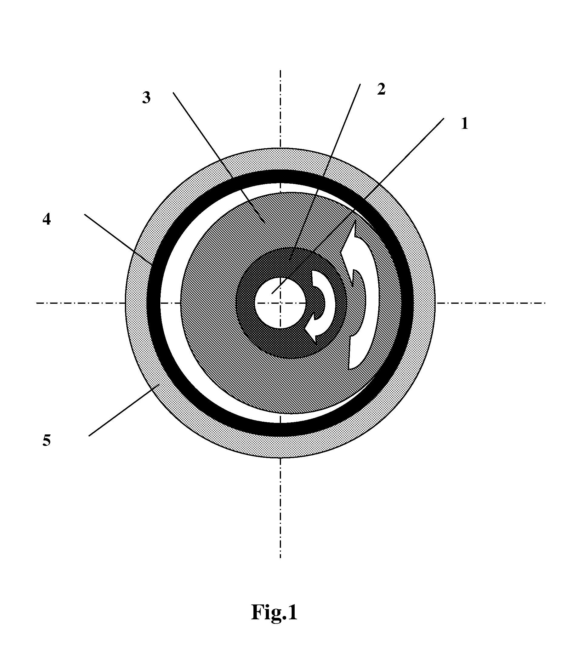
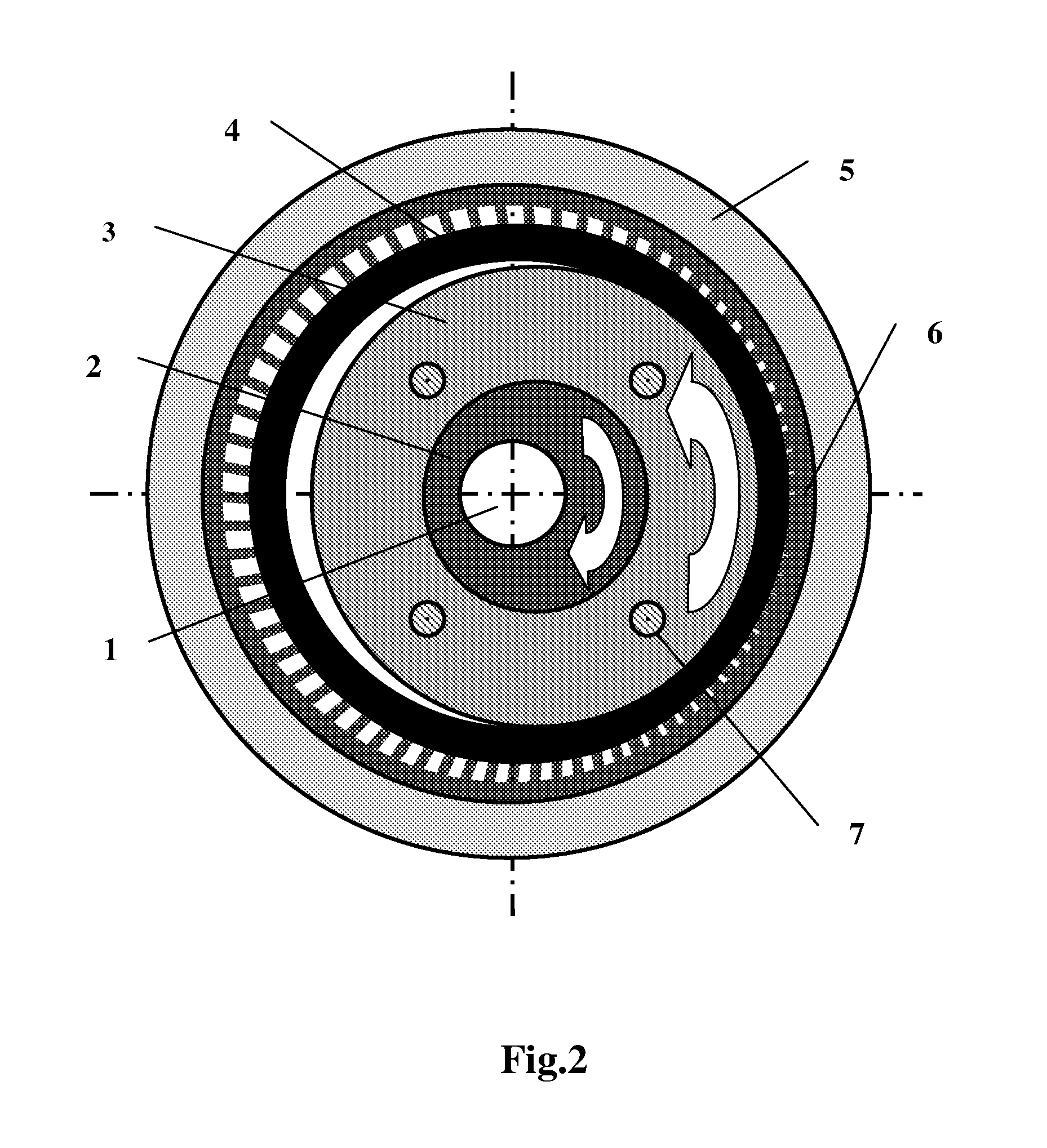
[0013]The functioning principle of such a reducer can be seen in FIG. 1 which is the first constructive modality where the rotational motion of the input element 1 makes the eccentric cam 2 moves in orbital motion which is reciprocal to and moving, the eccentric cam 2 transmits the orbital motion to the pulley 3. The pulley 3 rotates in the eccentric cam 2. The belt 4 makes the drivingly coupling between the pulley 3 and the external ring 5 to which is reciprocal to. In this case, the external ring 5 is reciprocal to the reducer structure therefore it does not turn. As represented in FIG. 1, the rotary motion of the input element 1 in one direction, makes the pulley 3 drivingly coupled to the external ring 5 rotates in an opposite direction. Without taking into account an eventual slipping between the pulley 3 and the belt 4, the transmission relation between the rotation of the input element 1 and the pulley 3 is given by the pitch diameter of the pulley 3 divided by the difference...


PUM


Abstract

It is an epicyclic gear system for use in speed reducer or overdrive, however using an inner pulley, an external ring and a driving belt or a tire instead of using toothed gears. The system particularity is an inner pulley drivingly coupled to an external ring and the torque transmission between the inner pulley and the external ring is done through a belt or a tire, as either the inner pulley or the external ring has orbital motion.

Description

FIELD OF THE INVENTION[0001]The present invention relates to a planetary gear mechanism used for speed reduction or overdrive and, in particular, to the use of one inner pulley drivingly connected by a drive belt or a tire to an outer ring, where either the inner pulley or the outer ring has orbital motion.BACKGROUND OF THE INVENTION[0002]Planetary or epicyclic gear systems for use in speed reducers are a long time known. One example of such system is described in U.S. Pat. No. 276,776, issued to George F. Clemons on May 1, 1883. There are known mechanisms of epicyclic speed reduction, which typically include a pinion gear in orbit coupled to an internally toothed gear. These transmissions make possible great speed reduction however there is the limiting factor, which is the precise aspect of the complicated teeth and the transmitted torque limitation due to the small contact area between the teeth of the gears.SUMMARY OF THE INVENTION[0003]The present invention provides other possi...

Claims


Application Information

Patent Timeline
Patent Type & Authority Applications(United States)
IPC IPC(8): F16H7/14
CPCF16H13/06
Inventor GRAVIO, VALMOR DA CUNHA
Owner GRAVIO VALMOR CUNHA
Why Eureka
Try Eureka