Internal sinus manipulation (ISM) procedure for facilitating sinus floor augmentation in dental procedures

a technology of sinus floor and injection technique, applied in the field of internal sinus manipulation (ism) procedure for facilitating sinus floor augmentation in dental procedures, can solve the problems of increasing patient discomfort, limited amount of sinus floor and bone augmentation, and controlling the osteotome tapping for

Inactive Publication Date: 2008-07-03
YAMADA JASON M
View PDF6 Cites 27 Cited by
  • Summary
  • Abstract
  • Description
  • Claims
  • Application Information

AI Technical Summary

Benefits of technology

[0013]The simultaneous lifting and lateral separation of the portion of sinus membrane from the sinus floor may be accomplished using a sinus lifting tool that includes a disk-shaped tip and an angled neck. The disk-shaped tip is designed to release the sinus membrane from the bony wall of sinus floor. The angled neck is designed to aid in the proper positioning of the working tip. An inflection portion of the angled neck extending from the working tip allows the clinician to feel the tension of the sinus membrane and to determine the amount of initial lateral and vertical membrane reflection. The procedure for membrane release and elevation should be continued until a planned amount of sinus extension is achieved and the pocket is defined.

Problems solved by technology

For example, because of inadequate bone in the posterior maxilla of some dental patients, augmentation of the sinus floor is required before placement of a dental implant.
However, post-operative complications such as pain or swelling due to extensive surgical trauma may increase patient discomfort.
However, the amount of augmentation of the sinus floor and the volume of bone created is limited using the foregoing techniques and it is reportedly difficult in many cases to control the osteotome tapping force in order to produce effective membrane lifting without membrane perforation and on occasion the tapping procedure to fracture the sinus floor or to add bone graft material causes discomfort to the patient during the surgery.

Method used


Image

  • Internal sinus manipulation (ISM) procedure for facilitating sinus floor augmentation in dental procedures
  • Internal sinus manipulation (ISM) procedure for facilitating sinus floor augmentation in dental procedures
  • Internal sinus manipulation (ISM) procedure for facilitating sinus floor augmentation in dental procedures

Examples


Embodiment Construction

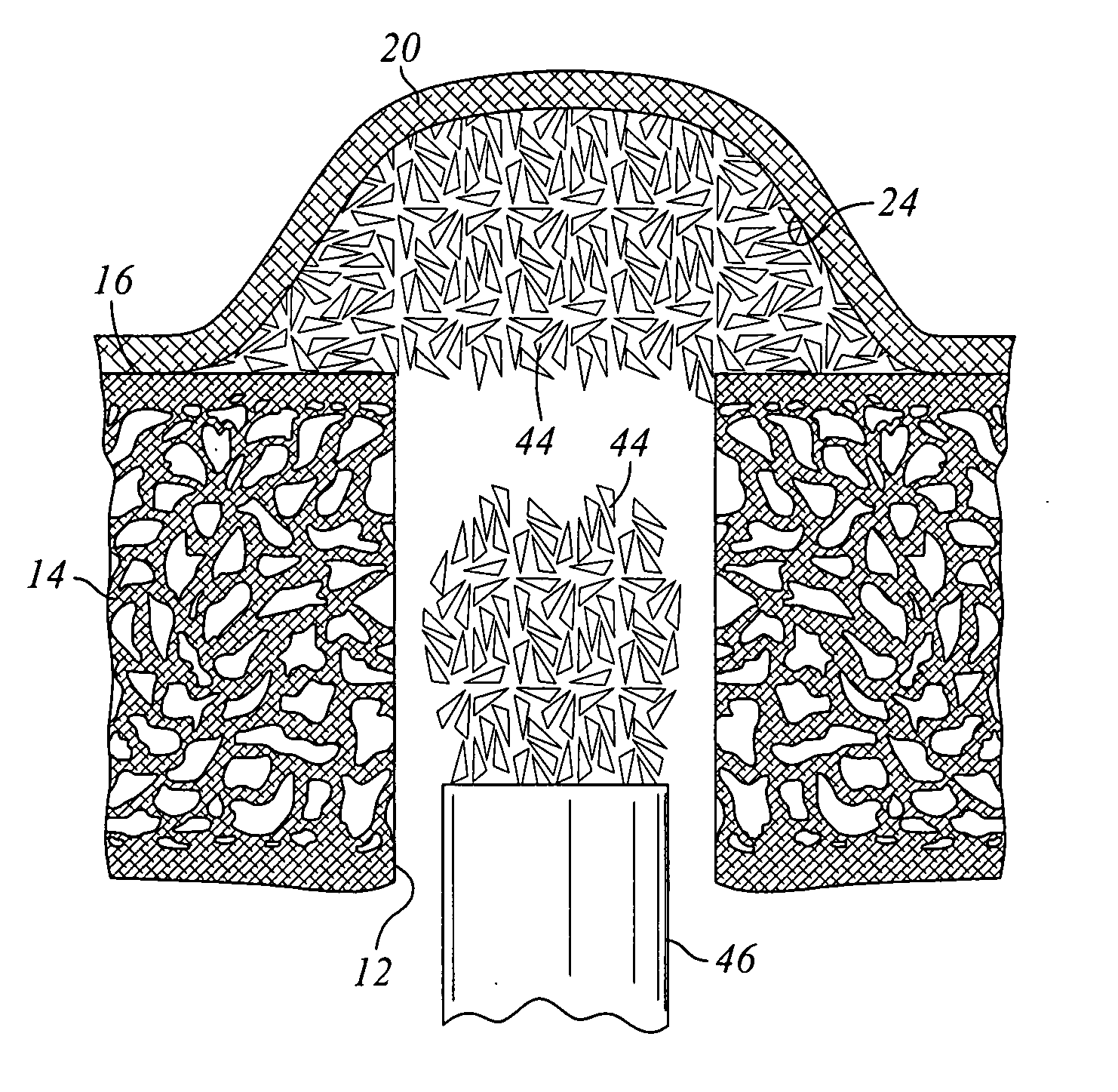
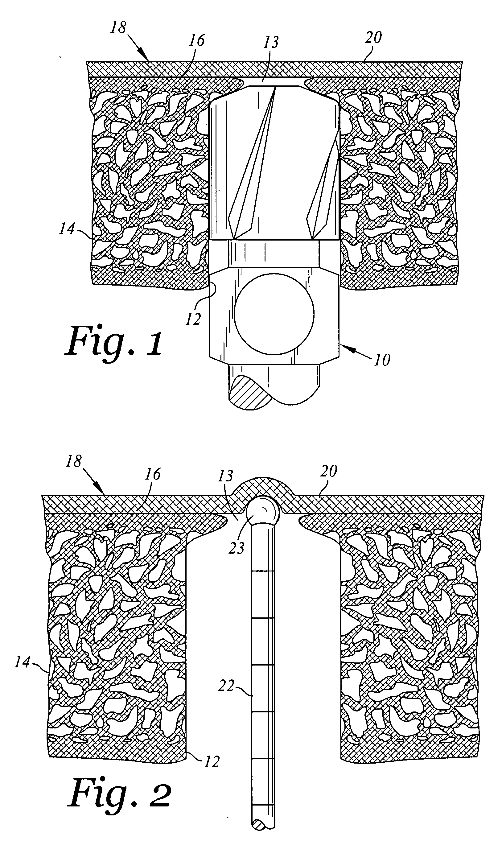
[0025]In practice, prior to beginning the ISM procedure generally described above, a patient treatment plan should be established based on clinical evaluation, diagnostic wax-up on a study cast and radiographic information from a periapical radiograph, a panoramic radiograph or a computerized tomogram. Then, after full thickness flap elevation or through a flapless procedure, a standard implant osteotomy drilling sequence is followed using a surgical guide, a round marker and subsequent twist drills. Such a drilling procedure is depicted in FIG. 1 where a standard twist drill 10 is shown forming a channel 12 in the bone 14 of in the maxillary posterior area of a patent where the bone is of insufficient thickness to effectively receive of a dental implant. As previously indicated, conventional twist drills or surgical round diamond burs can be used to drill up to the sinus floor 16, barely breaking through the existing bone, without perforating the sinus membrane 18, to expose throug...


PUM


Abstract

An internal sinus manipulation procedure for augmenting bone of a dental patient between the floor of the patient's sinus and a raised portion of the patient's sinus membrane comprising exposing a portion of the patient's sinus membrane immediately adjacent the floor of the patient's sinus followed by (i) a simultaneous and controlled lifting and lateral separation of the exposed portion of the sinus membrane from the sinus floor to form an open pocket between the sinus membrane and the sinus floor, (ii) introduction of a bone grafting material into the pocket and (iii) a compacting of the bone grafting material.

Description

RELATED PATENT APPLICATION[0001]The present application claims the benefit of U.S. Provisional Patent application Ser. No. 60 / 882,940 filed Dec. 31, 2006, which is herein incorporated by reference.BACKGROUND OF INVENTION[0002]The human posterior maxilla often presents dental clinicians with situations where there is a need to increase the available bone between the schneiderian (sinus) membrane and the floor of the maxillary antrum. For example, because of inadequate bone in the posterior maxilla of some dental patients, augmentation of the sinus floor is required before placement of a dental implant.[0003]An early sinus augmentation technique was presented by H. Tatum Jr. in 1977, later published in “Maxillary and Sinus Implant Reconstructions”, Dent Clin North Am 1986; 30(2):207-229 and first described by P. J. Boyne and R. A. James in 1980, “Grafting of the Maxillary Sinus Floor With Autogenous Marrow and Bone” J Oral Surg 1980; 38(8): 613-616.[0004]Originally Tatum accessed the ...

Claims


Application Information

Patent Timeline
Patent Type & Authority Applications(United States)
IPC IPC(8): A61F2/02
CPCA61B17/1655A61B17/1688A61F2/4601A61C8/0089A61C8/0092A61B2019/462A61B2090/062
Inventor YAMADA, JASON M.
Owner YAMADA JASON M
Why Eureka
Try Eureka