Drilling components and systems to dynamically control drilling dysfunctions and methods of drilling a well with same

a technology of drilling components and systems, applied in the direction of wellbore/well accessories, earthwork drilling and mining, flushing, etc., can solve the problems of premature failure of the cutting structure of the bit, the electrical and mechanical components of the downhole tool and collar, and the wear of each of the components of the drill string

Active Publication Date: 2008-07-10
BAKER HUGHES INC
View PDF23 Cites 122 Cited by
  • Summary
  • Abstract
  • Description
  • Claims
  • Application Information

AI Technical Summary

Benefits of technology

[0023]Further embodiments of the invention include methods of drilling comprising selectively controlling drilling fluid flow through a bottom hole assembly to adjust, for example bit rotational speed, axial force applied to a bit, or both. Other operational aspects of the bottom hole assembly may be adjusted, and any such adjustments may be effected responsive to measured values of downhole performance parameters during drilling.
[0024]Other features and advantages of the present invention will become apparent to those of ordinary skill in the art through consideration of the ensuing description, the accompanying drawings, and the appended claims.

Problems solved by technology

The drilling process causes significant wear on the each of the components of the drill string, in particular the drill bit and the BHA.
Whirl may cause high shocks to the bit and the downhole tools, leading to premature failure of the cutting structure of the bit, as well as the electrical and mechanical components of the downhole tools and collars.
Whirl may be a result of several factors, including a poorly balanced drill bit, i.e., one that has an unintended imbalance in the lateral forces imposed on the bit during the drilling process, the cutting elements on the drill bit engaging the undrilled formation at a depth of cut too shallow to adequately provide enough force to stabilize the bit, and other factors known to those having ordinary skill in the art.
Additionally, bit whirl may be caused in part by the cutting elements on the drill bit cutting too deeply into a formation, leading the bit to momentarily stop rotating, or stall.
Other drilling dysfunctions may result from a cutting element on the drill bit cutting too deeply into a formation.
For example, a drill bit may cut more formation material than can adequately be removed hydraulically from the face and the junk slots of the drill bit, possibly leading to a condition known as bit “balling” where the formation cuttings clog the waterways and junk slots of the bit, or the area around the BHA and the drill pipe may become filled with formation debris, possibly leading to a packed hole, stuck pipe, or other significant problems.
Another, separate problem involves drilling from a zone or stratum of higher formation compressive strength to a “softer” zone of lower strength.
The abruptly higher torque, in turn, may cause damage to the cutting elements and / or to the drill bit body itself.
In directional drilling, such a change may cause the tool face orientation of the directional (measuring-while-drilling, or MWD, or a steering tool) assembly to fluctuate, making it more difficult for the directional driller to follow the planned directional path for the drill bit.
In addition, a downhole motor, if used, may completely stall under a sudden torque increase.
Such interruptions in the drilling of a well can be time consuming and quite costly.
Similarly, drilling from a zone or stratum of lower formation compressive strength to a “harder” zone of higher compressive strength poses certain problems.
If the cutting elements do not engage the formation to a sufficient depth at a low WOB, the drill bit and the BHA may begin to whirl, possibly damaging the drill bit, sensors, and other BHA components.
As mentioned, such interruptions in the drilling of a well can be time consuming and quite costly, especially if the drill bit or the components of the drill string are damaged by the shocks induced by the whirl and have to be replaced.
These efforts, achieving varying degrees of success, are undoubtedly helpful, yet may be inadequate because the downhole environment encountered by the BHA may differ, sometimes significantly, from that anticipated during the drill bit and drill string component design and selection process.
However, the geology actually encountered in the well during the drilling process may have different characteristics or may be encountered at an unexpected depth from that initially predicted.
Thus, a drill bit or downhole tool that seemed particularly suited for an application initially may be, in reality, less than ideal or even fairly unsuitable for the actual application.
However, systems that identify drilling dysfunctions and recommend corrective actions may he inadequate in certain situations, as described herein.
First, the software programs and the closed loop drilling systems may require the active intervention of an operator at the surface to take corrective action to remedy certain drilling dysfunctions, which may pose several concerns.
This may occur because a portion of the surface WOB is lost via friction between the drill pipe and the wellbore, particularly in deviated wells.
Unfortunately, such an iterative process of making changes to the surface parameters and evaluating the resulting change on the drill bit and the drill string may take considerable time, during which the drilling dysfunction may be continuing.
For example, in cases of extremely high shocks (on the order of 100 times the force of gravity), which may be indicative of bit whirl, failure of the electronic components of the downhole tools (for example, of an MWD tool or of a logging while drilling (LWD) tool) or failure of the drill bit (e.g., damage to the cutting elements), or worse, may occur in minutes.
Should a downhole component fail prematurely, an unplanned trip to pull the tools out of the hole and replace the component may have to be made, significantly increasing the time and the cost of drilling a well.
Further compounding the time to remedy drilling dysfunctions because of the inherent inefficiencies in the transfer of inputs at the surface to the drill bit and the resulting time to iteratively reach an improved result, an inherent delay exists in transferring data gathered by the sensors on the tools in the wellbore to the surface.
However, the delay may have significant consequences in those instances in which a drilling dysfunction needs to be rectified extremely quickly before a catastrophic failure occurs, as discussed above.
Further, “noise” in the pressure signal may cause difficulty for the computer system attempting to decode the data encoded in the drilling pulses.
Worse, many drilling dysfunctions, in particular bit whirl and shocks to the drilling tools, may cause their own pressure fluctuations in the drilling fluid, further masking the encoded signal.
As a result, the computer system may incorrectly decode the pressure pulses or fail to decode the pulses at all while a drilling dysfunction occurs, resulting in either incorrect or no data from downhole being decoded.
Thus, drilling dysfunctions may pose serious difficulties during the drilling process and may be difficult to predict beforehand.
Further, drilling dysfunctions may often be hard to identify and remedy at the well site given the sometimes limited precision of the tools with which an operator has to work with at the surface.

Method used


Image

  • Drilling components and systems to dynamically control drilling dysfunctions and methods of drilling a well with same
  • Drilling components and systems to dynamically control drilling dysfunctions and methods of drilling a well with same
  • Drilling components and systems to dynamically control drilling dysfunctions and methods of drilling a well with same

Examples


example 1

[0065]An embodiment of the invention may be used to optimize the depth to which the cutting elements of the drill bit engage the formation and, hence, optimize the torque and / or the force applied to the drill bit during drilling. In so doing, the life of the drill bit and the drilling tools associated therewith in a BHA may be optimized, i.e., increased. In addition, the rate of penetration (ROP) may be optimized and the cost of drilling the well decreased.

[0066]It is usually desirable to maximize the ROP, at least until the point at which the drill bit or downhole tools wear too quickly and require premature replacement. The ROP often is a function, in part, of the WOB and the rpm of the drill bit and frequently increases as the WOB or the rpm increases. As one with ordinary skill may appreciate, however, the ROP is a complex function with many factors, of which WOB and rpm are only two of the factors over which control may be exerted.

[0067]In the case of roller cone bits, the wear...

example 2

[0082]While the foregoing example provides an example of occurrences in which the invention may prove useful, others may exist. For example, embodiments of the invention may prove useful in eliminating or at least reducing the severity of drilling dysfunctions that may occur during the drilling process. An example of such drilling dysfunctions may be the phenomenon known as stick-slip.

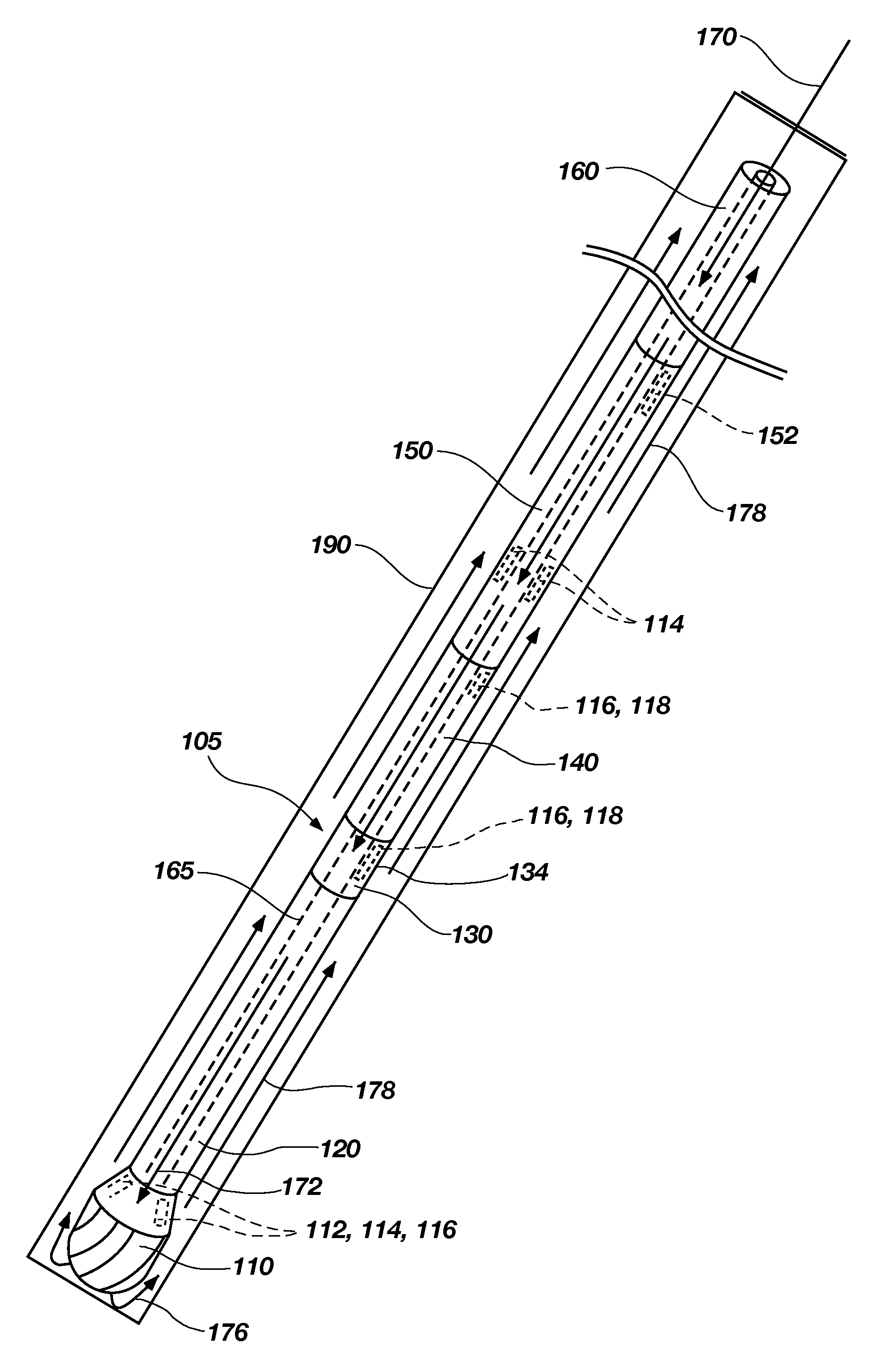
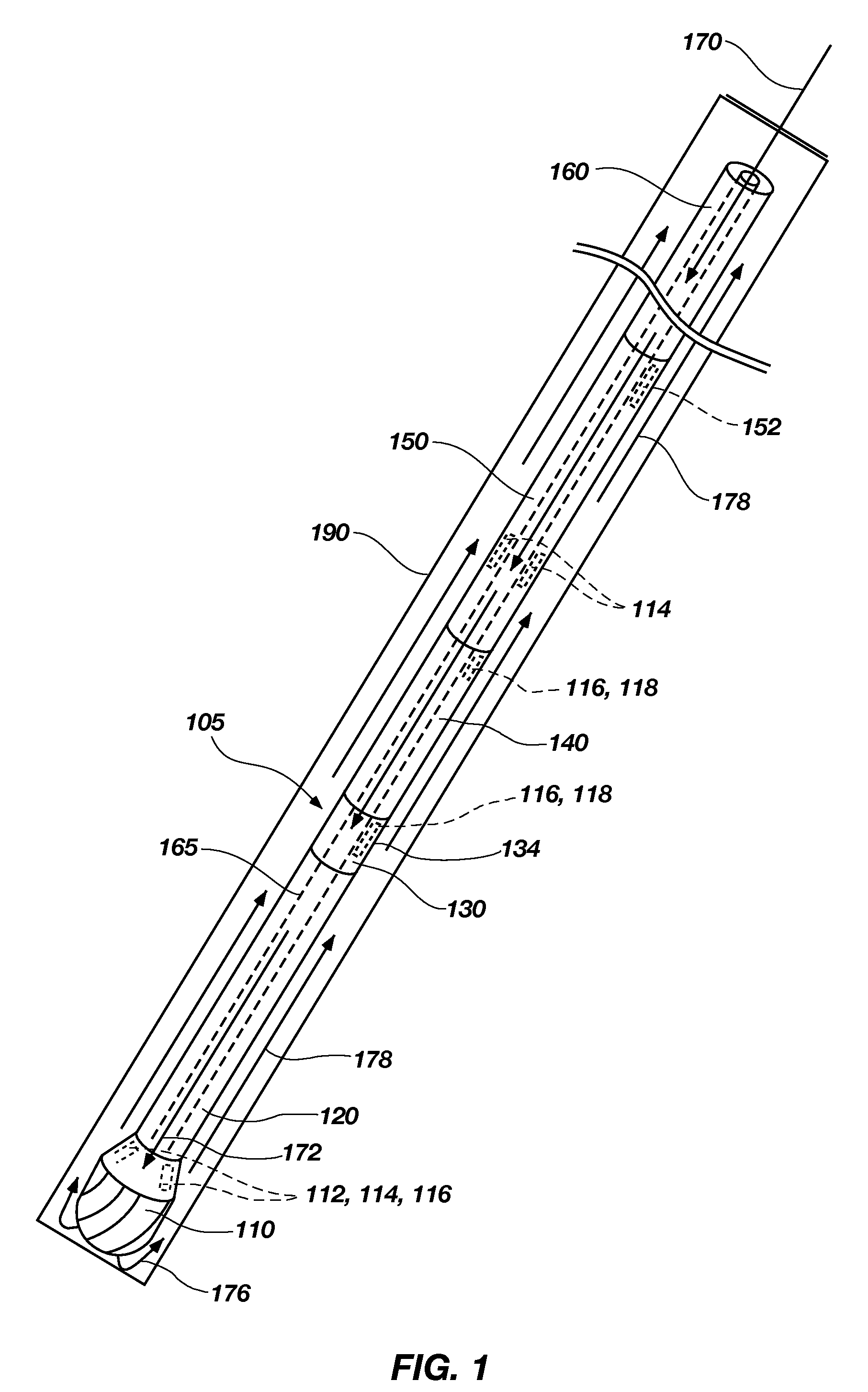
[0083]Stick-slip occurs when a portion of the BHA 105, usually the drill bit 110, stops rotating momentarily while the rest of the drill string 160 and the BHA 105 still rotate from the surface. This may occur because the cutting elements on the drill bit 110 engage the formation too deeply, causing the drill bit 110 to stop rotating and the downhole motor 120 to stall. An indication that this may have occurred is that the pressure of the drilling fluid 170 as measured at the stand pipe at the surface suddenly increases as the power section of the downhole motor 120 stops turning. In addition, sensors ...


PUM


Abstract

Drilling tools that may detect and dynamically adjust drilling parameters to enhance the drilling performance of a drilling system used to drill a well. The tools may include sensors, such as RPM, axial force for measuring the weight on a drill bit, torque, vibration, and other sensors known in the art. A processor may compare the data measured by the sensors against various drilling models to determine whether a drilling dysfunction is occurring and what remedial actions, if any, ought to be taken. The processor may command various tools within the bottom hole assembly (BHA), including a bypass valve assembly and / or a hydraulic thruster to take actions that may eliminate drilling dysfunctions or improve overall drilling performance. The processor may communicate with a measurement while drilling (MWD) assembly, which may transmit the data measured by the sensors, the present status of the tools, and any remedial actions taken to the surface.

Description

CROSS-REFERENCE TO RELATED APPLICATIONS[0001]This application claims the benefit of U.S. Provisional Patent Application Ser. No. 60 / 879,419, filed Jan. 8, 2007, the disclosure of which is hereby incorporated herein in its entirety by this reference.FIELD OF THE INVENTION[0002]Embodiments of the invention relate to bottom hole assemblies and components thereof that may detect drilling parameters and dynamically adjust operational aspects of the bottom hole assembly to enhance performance of a drill bit and other components of the bottom hole assembly, and to methods of drilling.BACKGROUND[0003]Hydrocarbons are obtained by drilling wells with a drill bit attached to a drill string that is rotated from the surface and, in some instances, by a downhole motor in addition to or in lieu of surface rotation. A drill bit that is used to drill through the earth is connected to what is termed a bottom hole assembly (BHA) that may include components such as, for example, one or more drill colla...

Claims


Application Information

Patent Timeline
Patent Type & Authority Applications(United States)
IPC IPC(8): E21B44/04
CPCE21B44/005E21B21/103
Inventor BRACKIN, VAN J.PASTUSEK, PAUL E.
Owner BAKER HUGHES INC
Why Eureka
Try Eureka