Method of Controlling an Image Capturing System, Image Capturing System and Digital Camera

Inactive Publication Date: 2008-07-10
ACTIVE OPTICS
View PDF12 Cites 18 Cited by
  • Summary
  • Abstract
  • Description
  • Claims
  • Application Information

AI Technical Summary

Benefits of technology

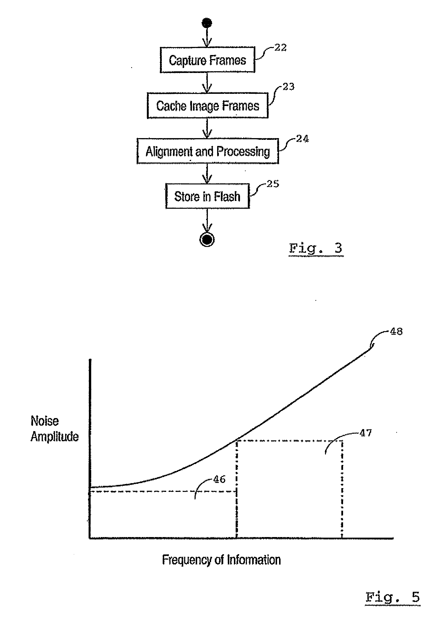
[0037]Because the higher resolution image also has a higher noise level, but is only really needed to provide image information with a high spatial frequency, the noise l

Problems solved by technology

Because not all image frames have the same, higher, resolution, the total time

Method used


Image

  • Method of Controlling an Image Capturing System, Image Capturing System and Digital Camera
  • Method of Controlling an Image Capturing System, Image Capturing System and Digital Camera
  • Method of Controlling an Image Capturing System, Image Capturing System and Digital Camera

Examples


Example

[0066]In a first embodiment, the size of the aperture 4, as well as the lighting conditions, are kept constant between exposures. The desired exposure time for the combined final image is unevenly distributed over the image frames. In one embodiment, the number of image frames is selected to keep the exposure time interval for each image frame below a certain threshold level. For instance, this threshold level is pre-determined at 1 / 60 second, as this is considered the lowest shutter speed to capture a steady image for the average photographer.

[0067]In one variant, the exposure time is varied randomly between frames. In another embodiment, settings of the image capturing system, in this case the exposure time, are adjusted before several further captures of a frame in such a manner that at least a maximum of the scale on which intensity values for each pixel are recorded changes substantially uniformly in value with each adjustment. This has the advantage of resulting in a more accu...

Example

[0076]A second embodiment of the method of forming a combined final image is illustrated in FIGS. 4A-4C. A first array 26 of pixel values encodes light intensity levels at each of a respective number of pixel positions in a first image frame. Each intensity value represents a light level in an area surrounding a pixel position. The same is true for a second array 27 of pixel values, encoding a second image frame. The first and second image frames represent the same captured scene. It will be assumed herein that the image frames encoded by the first and second arrays 26,27 have previously been aligned. There are known methods for aligning images to sub-pixel resolution, for example using sample points.

[0077]The first array 26 of pixel values is divided into four blocks 28-31. The second array 27 of pixel values is divided into the same number of blocks 32-35. A first block 28 in the first array 26 corresponds to a first block 32 in the second array 27, i.e. represents a substantially...


PUM


Abstract

A method of controlling an image capturing system comprising an interface for receiving an external trigger to capture an image, and an image capturing device provided with a photosensitive area and an array of pixel cells, each pixel cell including a device for generating a signal indicative of the intensity of light falling on an associated part of the photosensitive area, which image capturing device is further provided with readout circuitry for generating an array of pixel values to capture an image frame at a set spatial resolution, such that each pixel value represents an integral of the signal or signals generated in at least one of the pixel cells in an associated one of a number of areas over an exposure time interval, the number of areas being determined by the set spatial resolution, the areas together covering a region of the photosensitive area corresponding to a region in the image, comprises receiving an external trigger to capture an image, and, in response to the external trigger, directing the image capturing device to capture at least two image frames by generating respective arrays of pixel values representing integrals over respective consecutive exposure time intervals. The spatial resolutions of at least two of the captured image frames are set to different values.

Description

CROSS-REFERENCE TO RELATED APPLICATION[0001]The present application is a Section 371 National Stage Application of and claims priority of International patent application Serial No. PCT / EP2005 / 052121, filed May 10, 2005, and published as WO 2006 / 119802 in English.BACKGROUND OF THE INVENTION[0002]The invention relates to a method of controlling an image capturing system comprising an interface for receiving an external trigger to capture an image, and an image capturing device provided with a photosensitive area and an array of pixel cells, each pixel cell including a device for generating a signal indicative of the intensity of light falling on an associated part of the photosensitive area, which image capturing device is further provided with readout circuitry for generating an array of pixel values to capture an image frame at a set spatial resolution, such that each pixel value represents an integral of the signal or signals generated in at least one of the pixel cells in an asso...

Claims


Application Information

Patent Timeline
IPC IPC(8): H04N5/228
CPCH04N3/1562H04N5/2352H04N5/23232H04N23/951H04N23/72H04N25/42H04N25/443
Inventor WAJS, ANDREW AUGUSTINE
Owner ACTIVE OPTICS
Why Eureka
Try Eureka