Two Dimensional Image Forming Device

a two-dimensional image and forming device technology, applied in the field of two-dimensional image forming devices, can solve the problems of unable to display a pure single color, unable to so as to reduce the noise of speckle noise, reduce the size of the optical system, and reduce the loss of light

Active Publication Date: 2008-07-10
PANASONIC CORP
View PDF8 Cites 34 Cited by
  • Summary
  • Abstract
  • Description
  • Claims
  • Application Information

AI Technical Summary

Benefits of technology

[0013]In the two dimensional image forming device, not only is it possible to reduce speckle noises, bu

Problems solved by technology

In a projector using a lamp, because light having a continuous spectrum of a lamp light source is separated to three colors in RGB, each ray of RGB light has a continuous spectrum distribution, which makes it impossible to display a pure single color.
Incidentally, a problem with the display as above is so-called speckle noises occurring due to the use of a

Method used


Image

  • Two Dimensional Image Forming Device
  • Two Dimensional Image Forming Device
  • Two Dimensional Image Forming Device

Examples


first embodiment

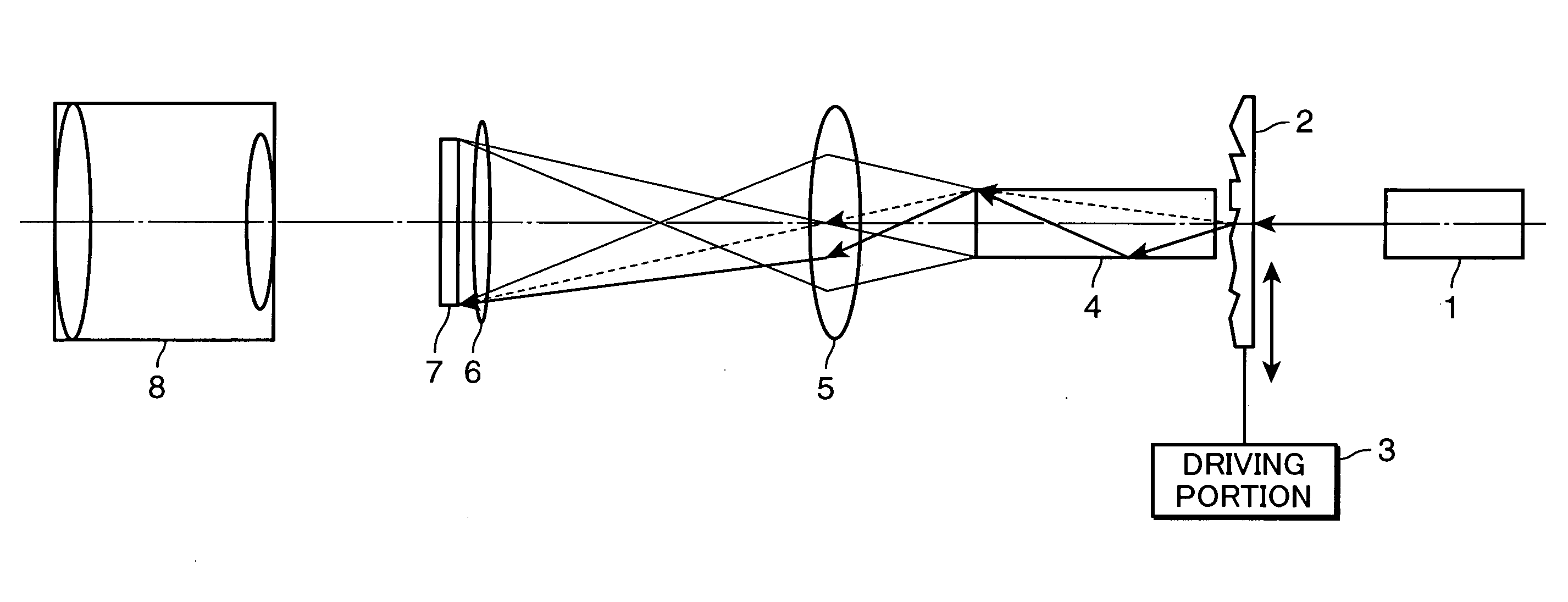
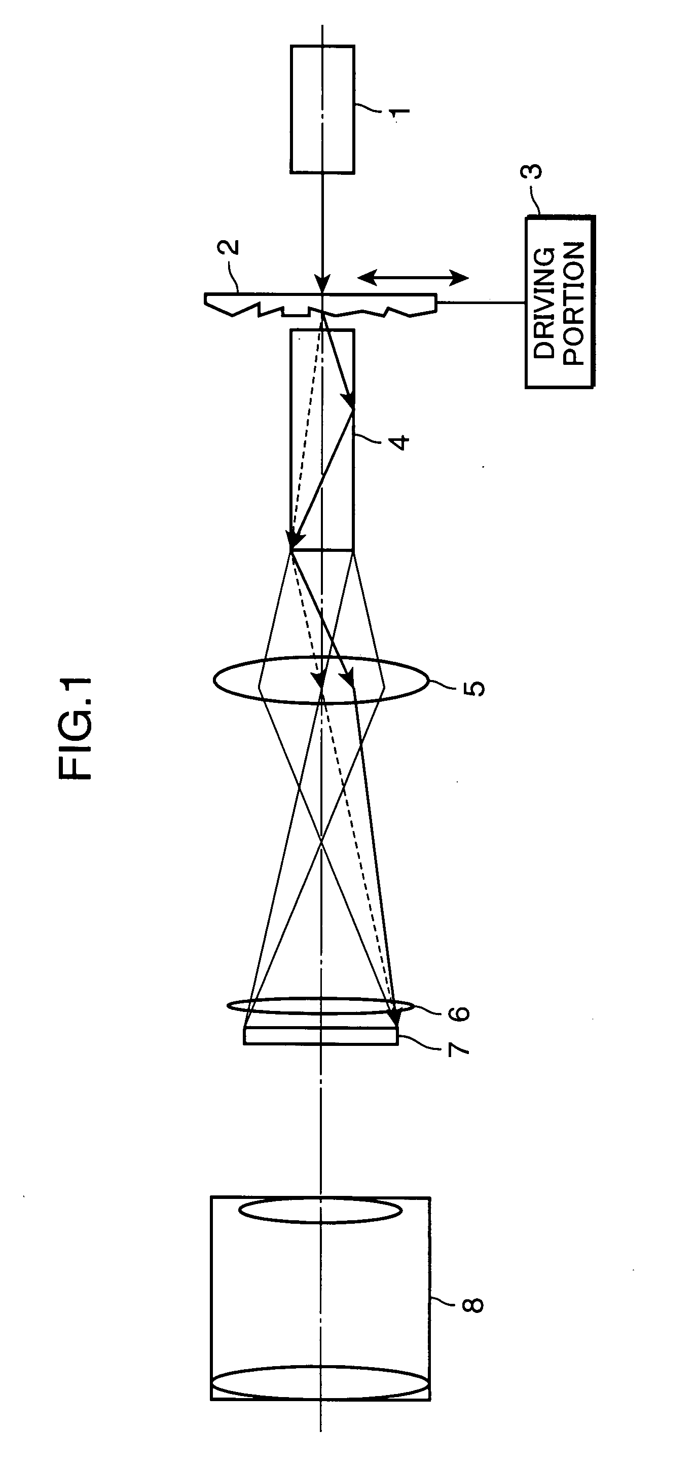
[0031]FIG. 1 is a view schematically showing the configuration of a two dimensional image forming device according to a first embodiment of the invention. The two dimensional image forming device shown in FIG. 1 includes a laser light source 1, a prism array 2, a driving portion 3, a rod integrator 4, a projection optical system 5, a field lens 6, a two dimensional spatial light modulation element 7, and a projection lens 8.

[0032]A light beam emitted from the laser light source 1, which is a coherent light source, passes through the prism array 2 and goes incident on the rod integrator 4. The light beam having undergone internal reflection repetitively inside the rod integrator 4 and eventually reached the exiting end thereof is projected onto the transmissive two dimensional spatial light modulation element 7 by the projection optical system 5 via the field lens 6. The two dimensional spatial light modulation element 7 is formed of liquid crystal shutters or the like, and modulates...

second embodiment

[0042]FIG. 3 is a view schematically showing the configuration of a two dimensional image forming device according to a second embodiment of the invention. A difference between the two dimensional image forming device shown in FIG. 3 and the two dimensional image forming device shown in FIG. 1 is that a polarization beam splitter 9 is additionally provided, the transmissive two dimensional spatial light modulation element 7 is replaced with a reflective two dimensional spatial light modulation element 7a, and the projection lens 8 is disposed above the polarization beam splitter 9. Because the rest is the same as the two dimensional image forming device shown in FIG. 1, like portions are labeled with like reference numerals and detailed descriptions thereof are omitted herein.

[0043]The reflective two dimensional spatial light modulation element 7a is formed of, for example, a two dimensional spatial light modulation element called an LCDS (Liquid Crystal On Silicon) formed by provid...

third embodiment

[0046]FIG. 4 is a view schematically showing the configuration of a two dimensional image forming device according to a third embodiment of the invention. FIG. 5 is a schematic perspective view used to describe chiefly the configuration of a lenticular lens shown in FIG. 4. In this embodiment, a light beam is deflected by disposing two lenticular lenses 10a and 10b respectively rotated by two driving portions 3a and 3b in a space from the laser light source 1 to the rod integrator 4. Because the rest is the same as the two dimensional image forming device shown in FIG. 1, like portions are labeled with like reference numerals and detailed descriptions thereof are omitted herein.

[0047]Each of the lenticular lenses 10a and 10b used in this embodiment forms a lenticular lens by forming smooth concavo-convex shapes like a corrugated plate on a circular ring area of a circular disc substrate. The concavo-convex shapes are disposed so that the direction of the concavo-convex shapes is ori...


PUM


Abstract

A two dimensional image forming device includes: a laser light source (1) which is a coherent light source; a prism array (2) that changes the traveling direction of a beam exiting from the laser light source (1); a driving portion (3) that rotates the prism array (2); a rod integrator (4) that guides the exiting beam deflected on the prism array (2) while allowing the beam to undergo internal reflection; a projection optical system (5) that projects the exiting end face of the rod, integrator (4) onto a two dimensional spatial light modulation element (7); and a projection lens (8) that projects light exiting from the two dimensional spatial light modulation element (7) onto a specific plane within a space.

Description

TECHNICAL FIELD[0001]The present invention relates to a two dimensional image forming device using a coherent light source as a light source. More particularly, the present invention relates to a two dimensional image forming device having means for reducing speckle noises appearing within the display.BACKGROUND ART[0002]FIG. 16 schematically shows the configuration of a conventional laser display. Each of light beams from laser light sources 101a through 101c for three colors in RGB is expanded by a beam expander 102 and irradiated to a two dimensional spatial light modulation element 107 by a light integrator 103. The light integrator 103 is a fly's eye lens in which rectangular unit lenses are arrayed two dimensionally, and a light intensity distribution of substantially the Gaussian distribution forms an almost uniform rectangular shape on the two dimensional spatial light modulation element 107 so as to irradiate the two dimensional spatial light modulation element 107 at unifo...

Claims


Application Information

Patent Timeline
IPC IPC(8): G02B26/08G02B13/20
CPCG02B27/48
Inventor KASAZUMI, KENICHI
Owner PANASONIC CORP
Why Eureka
Try Eureka