Double-facetted illumination system with attenuator elements on the pupil facet mirror

a technology of attenuator elements and illumination systems, which is applied in the field of illumination systems, can solve the problems of aforementioned ellipticity errors, large ellipticity errors in the exit pupil of the illumination system,

Inactive Publication Date: 2008-07-10
CARL ZEISS SMT GMBH
View PDF14 Cites 42 Cited by
  • Summary
  • Abstract
  • Description
  • Claims
  • Application Information

AI Technical Summary

Problems solved by technology

The disadvantageous aspect in the previously described systems according to the state of the art was that large ellipticity errors can occur in the exit pupil of the illumination system which coincides with the entrance ...

Method used


Image

  • Double-facetted illumination system with attenuator elements on the pupil facet mirror
  • Double-facetted illumination system with attenuator elements on the pupil facet mirror
  • Double-facetted illumination system with attenuator elements on the pupil facet mirror

Examples


Embodiment Construction

[0036]The invention will be explained below by way of examples by reference to the enclosed drawings, wherein:

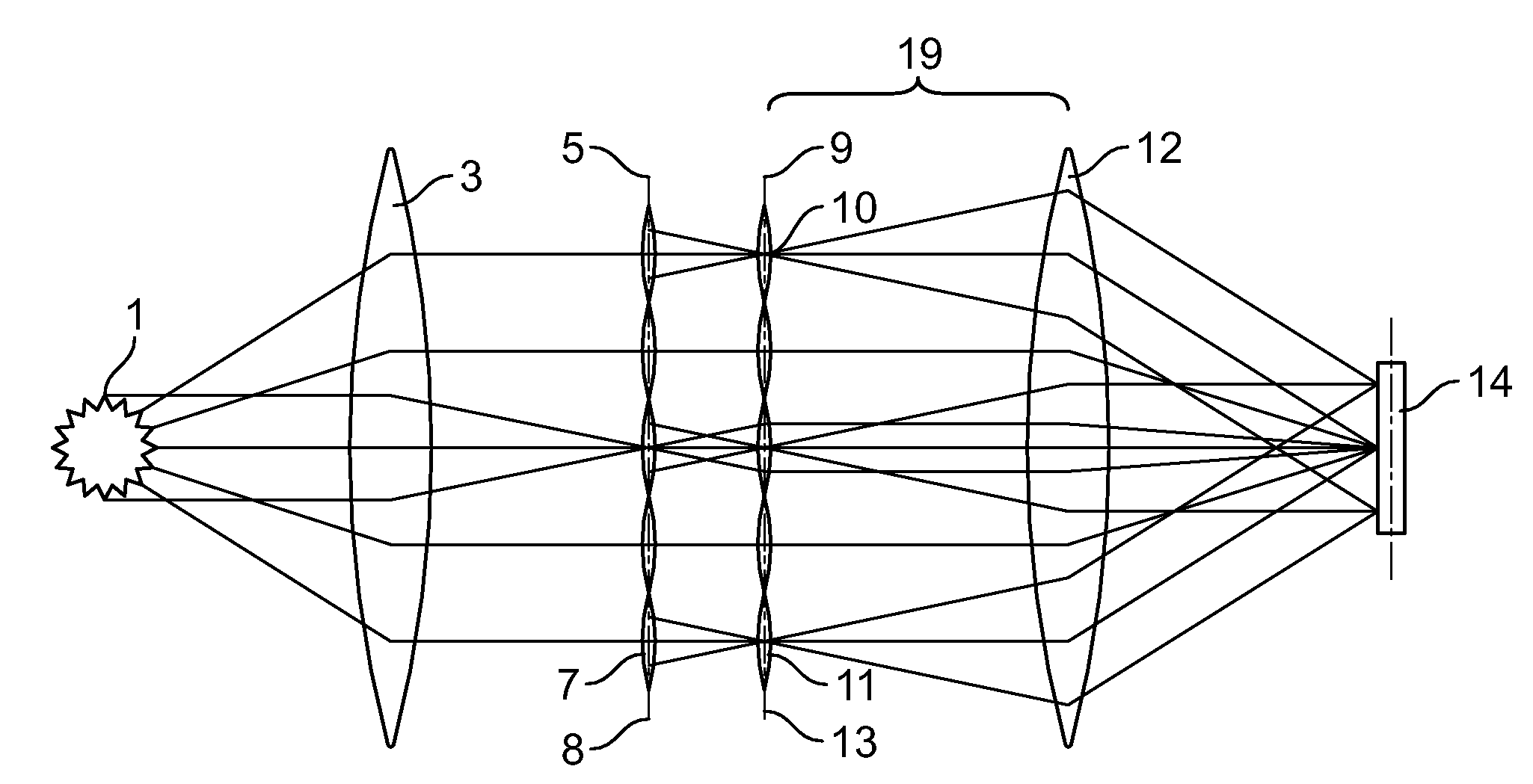
[0037]FIG. 1 shows an elementary diagram of a double-facetted illumination system;

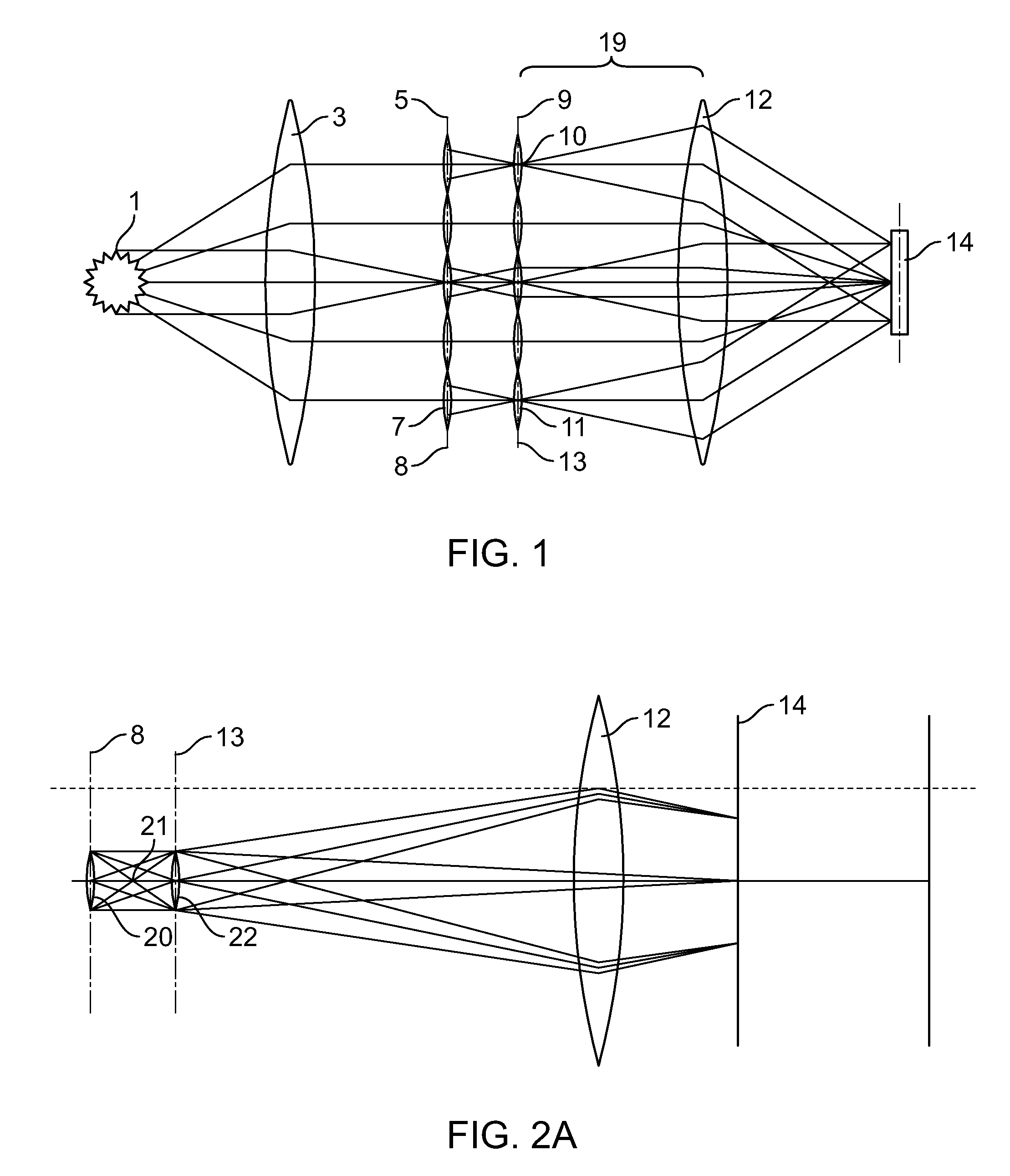
[0038]FIG. 2A shows the beam path of a double-facetted illumination system from a light source up to the field plane;

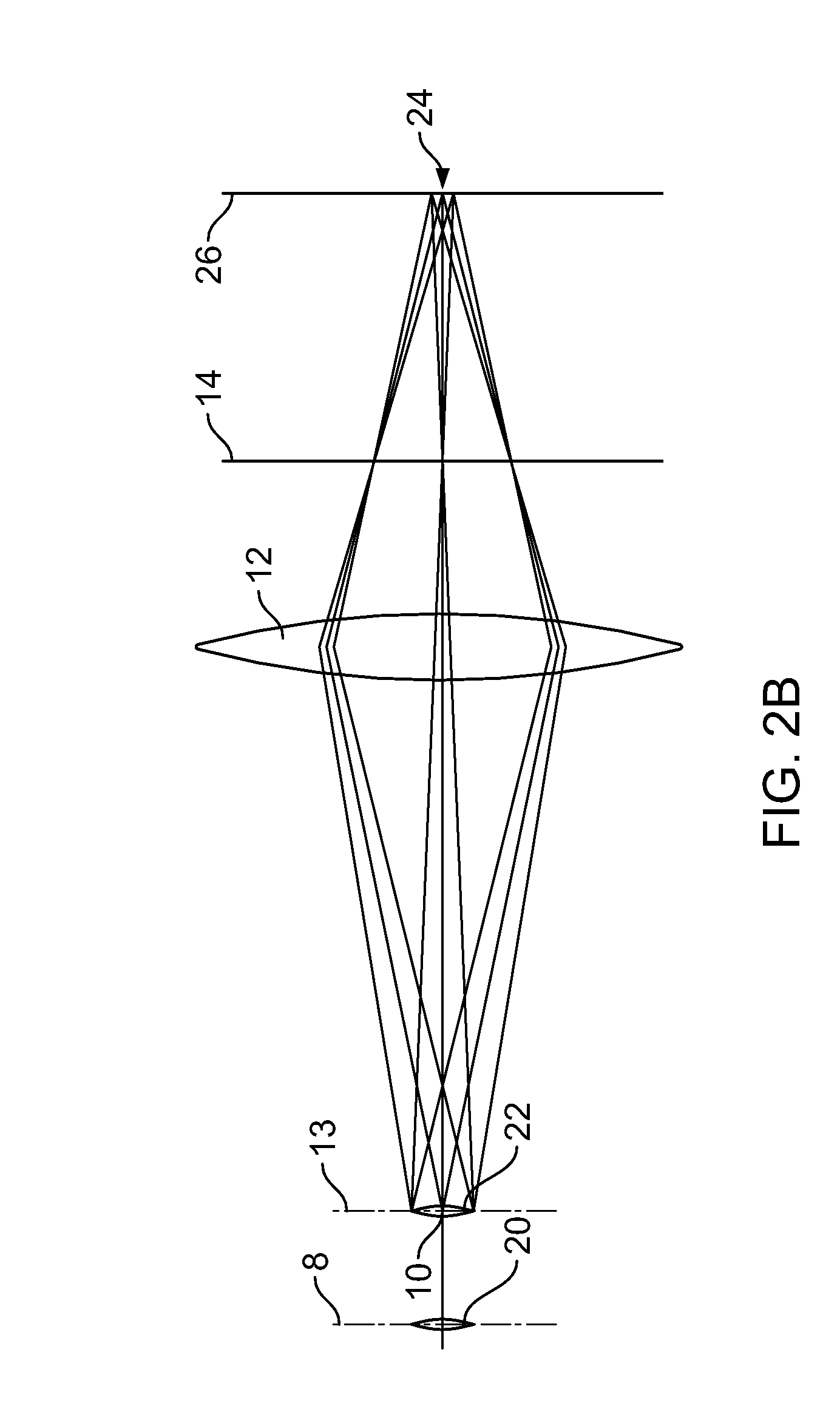
[0039]FIG. 2B shows the beam path of a double-facetted illumination system from a light source up to the exit pupil plane;

[0040]FIG. 3a shows the principal configuration of an illumination system;

[0041]FIG. 3b shows the exit pupil in the exit pupil plane;

[0042]FIG. 4 shows a first facetted optical element with field raster elements;

[0043]FIG. 5 shows a second facetted optical element with pupil facets;

[0044]FIG. 6 shows an illuminated ring field in the field plane of the illumination system;

[0045]FIG. 7 shows a pupil illumination in the exit pupil plane without correction by an attenuator;

[0046]FIG. 8 shows a pupil illumination in the exit pupil plane with correction by an attenu...


PUM


Abstract

The invention relates to an illumination system with a light source emitting radiation with a wavelength ≦193 nm, especially radiation in the EUV wavelength range. The invention comprises a first facetted optical element in a first plane with at least a first and second field raster element which receive the light of the light source and divide the same into a first and second bundle of light; a optical component comprising at least a second facetted optical element in a second plane with a first and second pupil raster element, with the first light bundle impinging upon the first pupil raster element and the second light bundle impinging upon the second pupil raster element, with an attenuator being arranged in or close to the second plane or a plane conjugated to the second plane at least in the first light bundle extending from the first field raster element to the first pupil raster element, wherein the optical component images the first and second field raster element into a field plane.

Description

CROSS REFERENCE TO RELATED APPLICATIONS[0001]This application is a continuation application and claims benefit of International Patent Application Serial No. PCT / EP2006 / 005857, filed on Jun. 19, 2006, which claims benefit and priority under § 119 USC of U.S. provisional application 60 / 692,700, filed in the US Patent and Trademark Office on Jun. 21, 2005. The entire contents of these applications are incorporated herein in its entirety.FIELD OF THE INVENTION[0002]The invention relates to an illumination system with a light source, with the light source emitting radiation with wavelengths ≦193 nm, especially radiation in the EUV wavelength range. The illumination system is a double facetted illumination system. In a double facetted illumination system, the illumination system comprises at least two facetted optical elements, a first facetted optical element and a second facetted optical element. The facetted optical elements comprise a plurality of facets which are also known as raste...

Claims


Application Information

Patent Timeline
IPC IPC(8): G21K5/00G02B13/14
CPCG03F7/70075G03F7/70191G03F7/70083
Inventor SINGER, WOLFGANGHAINZ, JOACHIMSCHUBERT, ERICH
Owner CARL ZEISS SMT GMBH
Why Eureka
Try Eureka