Pressure burst free high capacity cryopump

a high-capacity, pressure-bursting technology, applied in the direction of positive-displacement liquid engines, lighting and heating apparatus, separation processes, etc., can solve the problems of affecting the quality of condensed gases, so as to minimize the stress of crack formation and minimize condensation.

Active Publication Date: 2008-07-17
EDWARDS VACUUM LLC
View PDF19 Cites 15 Cited by
  • Summary
  • Abstract
  • Description
  • Claims
  • Application Information

AI Technical Summary

Benefits of technology

[0012]In another embodiment, a cryopump has a refrigerator with at least first and second stages. The second stage includes a cylinder. The cryopump also includes a radiation shield which surrounds the second stage and is in thermal contact with the first stage. A second stage cylinder shield is in thermal contact with the coldest section of the second stage and surrounds the cylinder. A passageway with a uniform temperature differential is formed between the cylinder shield and an extension piece that is in thermal contact with the first stage or in contact with the radiation shield. Molecular collisions with, and condensation on, the cold surface of the cylinder shield are assured to tightly bond the gas molecules to the cylinder shield and to prevent condensation on the second stage refrigerator cylinder.
[0014]According to another aspect of the present disclosure, a cryopump has a refrigerator with at least first and second stages. The cryopump also has a radiation shield which surrounds the second stage and that is in thermal contact with the first stage. The cryopump also has a second stage array supporting adsorbent in thermal contact with the second stage. The second stage array includes a primary condensing surface, protected surfaces having adsorbent, and non-primary condensing surfaces. The non-primary condensing surfaces include surface protrusions formed on a surface where the condensed frost aggregates. The protrusions reduce crack-forming stress in the condensed deposits as gas is deposited on the non-primary condensing surfaces.
[0016]The cryopump can include that the radiation shield includes a sealed diode hole, or an occlusion generally located to fill where a purge hole is located on the radiation shield. The radiation shield can include a baffle located over the drain hole to redirect gas from the non-primary condensing surface to the primary condensing surface to capture the gas and prevent a pressure excursion. The cryopump may include a surface that forms a non-contiguous film of condensed material as the gas is deposited on the non-primary condensing surface. The primary condensing surface includes a notch to prevent condensation from thermally contacting surfaces in contact with the radiation shield. The surfaces can be about 100 degrees Kelvin. The surface may form a deposited gas film with a non-uniform thickness. The non-uniform film thickness prevents cracking of the deposited film.
[0017]According to another embodiment, the cryopump includes a refrigerator having at least first and second stages and a radiation shield which surrounds the second stage, which is in thermal contact with the first stage. The cryopump includes a second stage array supporting adsorbent in thermal contact with the second stage. The second stage array includes a primary condensing surface, protected surfaces having adsorbent, and non-primary condensing surfaces. The primary pumping surface includes a top plate being sectioned into a first section and a second section. The first section and the second section are joined by a rigid connection that prevents relative movement of deposited condensation formed on the first section and the second section.
[0020]In another embodiment, there is provided a method of managing growth of condensation on a primary pumping surface formed from a first section and a second section of a top plate. The method includes blocking the flow from an annular spaced defined between the vacuum vessel and the radiation shield. The method also has the steps of redirecting the flow to the primary pumping-surface, and condensing the gases at the primary pumping surface to form thick frost. The method also has the step of mechanically coupling the first section and the second section to one another in a rigid manner. The rigid connection prevents condensation, which is deposited on the first section from moving and contacting the condensation deposited on the second section during operation of a pump.
[0021]In another embodiment, the cryopump includes a refrigerator having at least first and second stages and a radiation shield which surrounds the second stage and is in thermal contact with the first stage. The cryopump also includes a primary pumping surface supporting adsorbent, which is in thermal contact with the second stage. The primary pumping surface includes a primary condensing surface, protected surfaces having adsorbent, and non-primary condensing surfaces. The cryopump includes at least one of (i) a structure to minimize condensation on the non-primary condensing surfaces (i.e., a baffle, a flare, or an occlusion) and (ii) a second structure to minimize crack-forming stress (i.e., a protrusion or feature) in condensation deposits as gas is deposited on the non-primary condensing surfaces.

Problems solved by technology

The microstructure of the frost is complicated even for a simple binary mixture of pumped gases, widely used in most reactive sputtering applications in the semiconductor industry.
As the condensation becomes thicker, stress in the film becomes so great that the planar film will break or fracture and cause flakes, or solid fragments of the condensed gases.
These flakes are disfavored.

Method used


Image

  • Pressure burst free high capacity cryopump
  • Pressure burst free high capacity cryopump
  • Pressure burst free high capacity cryopump

Examples


Embodiment Construction

[0054]A description of example embodiments of the invention follows.

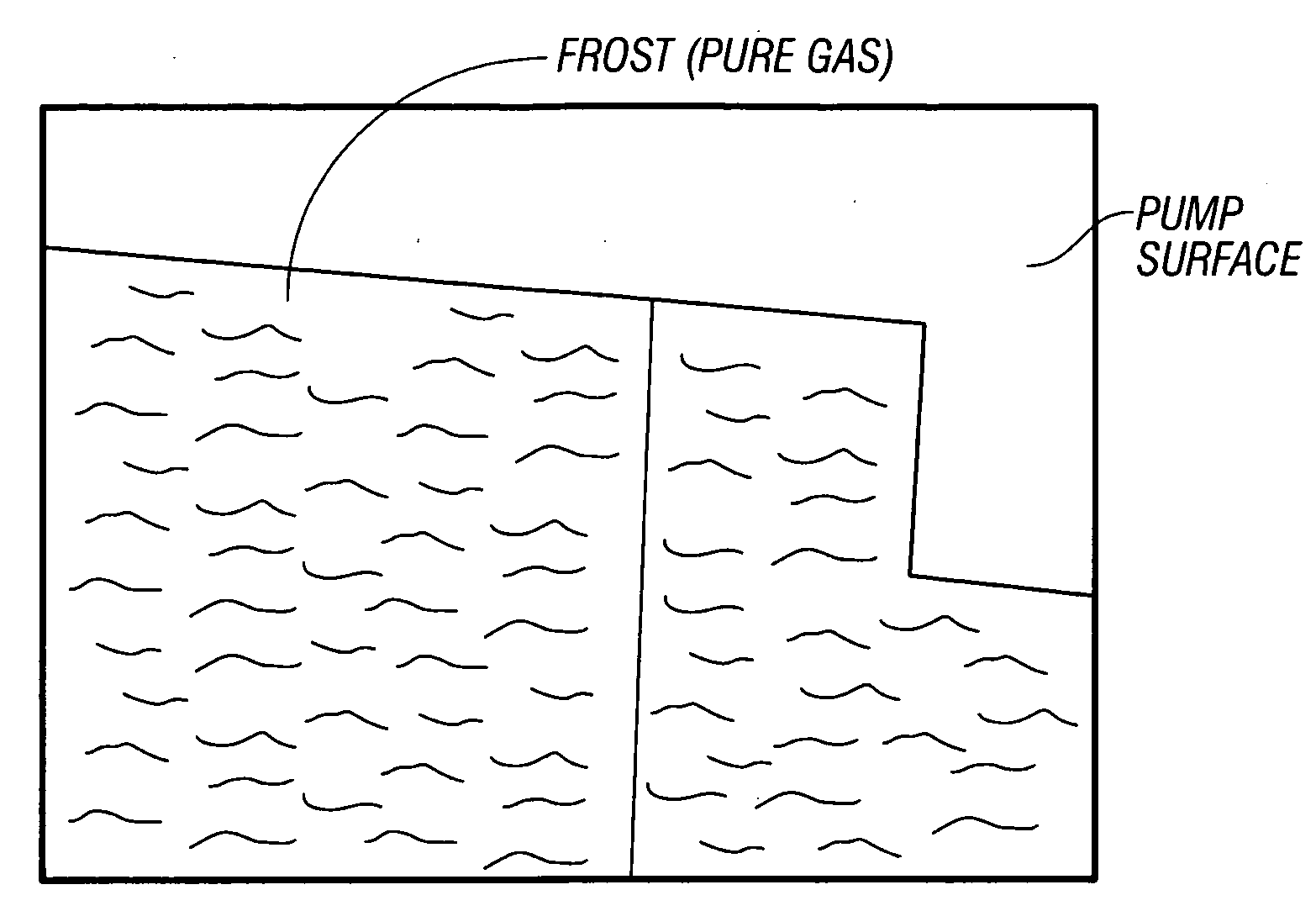
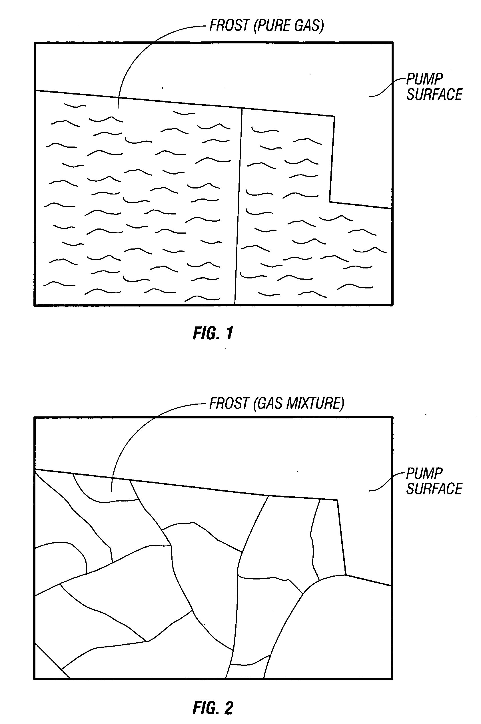
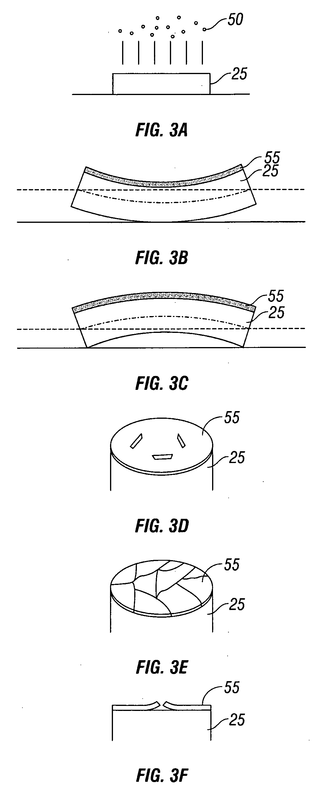
[0055]There exist two types of condensed frost films that forms on surfaces of the cryopump 10, a thick columnar shaped frost and a thin planar film. Turning now to FIGS. 5B and 5C, the columnar shaped frost (which is omitted from FIGS. 5B and 5C) may be formed on a primary condensing surface 15 of an array 20, while the planar film can be formed other non-primary condensing portions of a cryopump 10 (FIG. 5B). In one embodiment, the planar film may form on a bracket 25 positioned under the top plate 20 (FIG. 5B) of the array 10. This bracket 25 is a non-primary condensing surface 25 (FIG. 5B). Turning to FIG. 5D, gas may enter an annular space 40 that is located between a vacuum vessel 30 and a radiation shield 35. As shown in FIG. 5D, the gas will pass in to the annular space 40 in the direction of arrows A, B, and C instead of flowing to the top plate 15 of the array. The gas will then pass through a drain hole o...


PUM

PropertyMeasurementUnit
clearance distanceaaaaaaaaaa
pressureaaaaaaaaaa
vacuum pressureaaaaaaaaaa

Abstract

A cryopump includes a refrigerator with at least first and second stages. A radiation shield surrounds the second stage and is in thermal contact with the first stage. The radiation shield includes a drain hole to permit cryogenic fluid to traverse through the drain hole during regeneration. The cryopump also includes a primary pumping surface supporting adsorbent in thermal contact with the second stage. The second stage array assembly includes a primary condensing surface, protected surfaces having adsorbent, and non-primary condensing surfaces. A baffle is disposed over the drain hole. The baffle redirects gas from an annular space disposed between the radiation shield and the vacuum vessel that attempts to traverse through the drain hole to prevent the gas from condensing on a non-primary condensing surface. The baffle directs gas to condense on the primary condensing surface.

Description

CROSS REFERENCE TO RELATED PATENT APPLICATIONS[0001]This application claims priority to U.S. Provisional Patent Application Ser. No. 60 / 880,859, filed on Jan. 17, 2007 which is herein incorporated by reference in its entirety. This application also claims priority to U.S. Provisional Patent Application Ser. No. 60 / 897,666, filed on Jan. 26, 2007, which is herein incorporated by reference in its entirety.BACKGROUND OF THE INVENTION[0002]Cryopumps currently available, whether cooled by open or closed cryogenic cycles, generally follow the same design concept. A low temperature second stage array, usually operating in the range of 4 degrees to 25 degrees Kelvin, is the primary pumping surface. This surface is surrounded by a high temperature cylinder, usually operated in the temperature range of 50 degrees to 130 degrees Kelvin, which provides radiation shielding to the lower temperature array. The radiation shield generally comprises a housing. The housing is closed except at a locati...

Claims


Application Information

Patent Timeline
Patent Type & Authority Applications(United States)
IPC IPC(8): B01D8/00
CPCF04B37/08F04B37/02F04B39/121F25B9/14F05B2210/12F05B2210/11F05B2260/602Y10S417/901F04B37/085B01D8/00
Inventor BARTLETT, ALLEN J.DRISCOLL, MICHAEL A.EACOBACCI, MICHAEL J.JOHNSON, WILLIAM L.SULLIVAN, ROBERT P.SYSSOEV, SERGEISTIRA, MARK A.CASELLO, JOHN J.
Owner EDWARDS VACUUM LLC
Why Eureka
Try Eureka