Lighted welding torch

a welding torch and lighted technology, applied in the field of welding systems, can solve the problems of inconsistent cross section, weld formation, positioning and aligning electrodes in welding applications,

Inactive Publication Date: 2008-07-17
ILLINOIS TOOL WORKS INC
View PDF20 Cites 95 Cited by
  • Summary
  • Abstract
  • Description
  • Claims
  • Application Information

AI Technical Summary

Benefits of technology

[0008]Accordingly, there is a need for an improved welding system that provides for proper alignment of a torch and / or an electrode prior to and during the welding process. There is also a need for a technique for lighting welding locations, particularly to provide an indication of the position and orientation of a welding electrode and / or general lighting in the workplace.

Problems solved by technology

One difficulty in welding applications is positioning and aligning the electrode with respect to a desired weld location.
If the electrode is not aligned properly, the weld may be formed in the wrong location, the weld may have an inconsistent cross section, or the arc may be extinguished during the welding process.
This method of alignment is not precise and may lead to a weld in the wrong location, or a weld of low quality due to the electrode arcing at an improper distance from the work piece.
Moreover, most welding applications provide little or insufficient light to allow the welder to see any of the work piece or components once the arc is struck.

Method used


Image

  • Lighted welding torch
  • Lighted welding torch
  • Lighted welding torch

Examples


Embodiment Construction

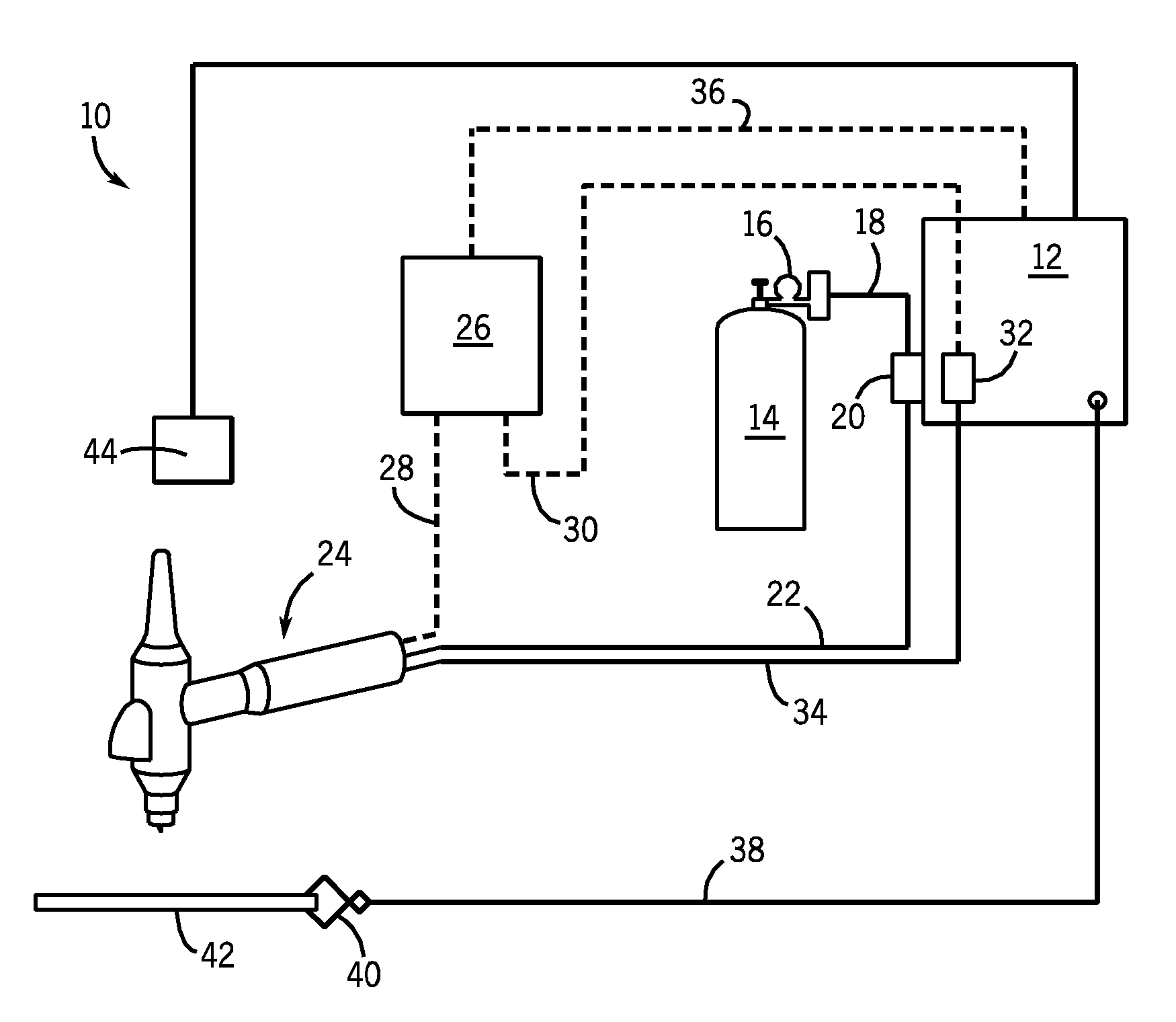
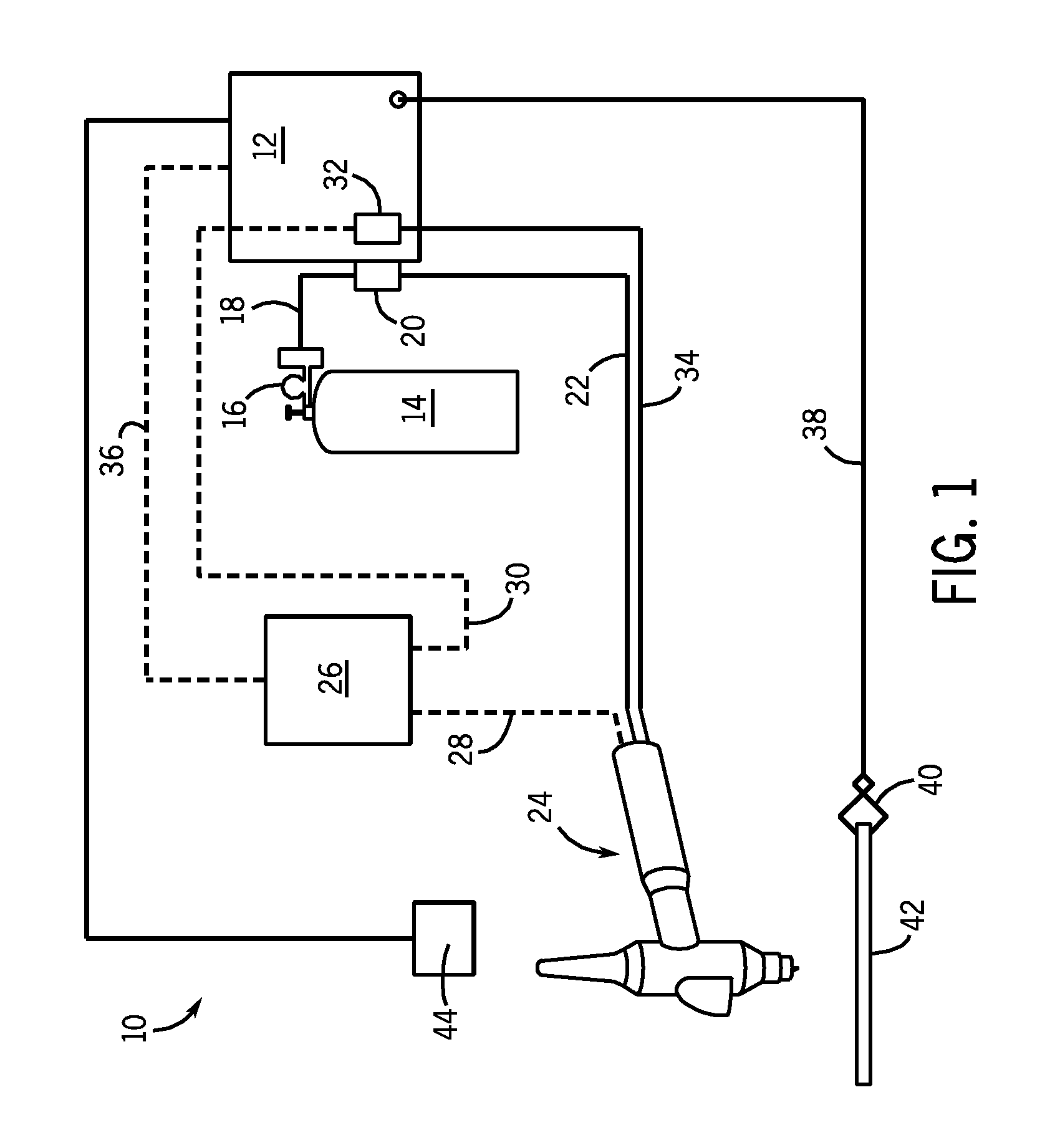
[0029]Referring now to FIG. 1, a welding system 10 in accordance with one embodiment of the present technique is illustrated. The welding system 10 may generally include multiple welding components and devices. As depicted, a TIG welding system 10 may include a power source 12, a shielding gas source 14, a cooling system 26 and a torch 24.

[0030]In the illustrated embodiment, the power source 12 provides power to the welding torch 24 via a supply conduit 22. The power source 12 may supply a DC current or AC current to the torch 24 depending on the desired application. For example, an AC current may be suited for welding aluminum or magnesium, and a DC current may be suited for welding stainless steels, nickel or titanium. In addition to matching the current to the material selection, the output of the power source 12 may be varied to obtain desired weld characteristics. For example, a low AC frequency (e.g., 60 Hz) current may generate a wide arc with shallow penetration of a work pi...


PUM

PropertyMeasurementUnit
distanceaaaaaaaaaa
AC frequencyaaaaaaaaaa

Abstract

Provided is system for aiding a welding operator in positioning a welding device. The system includes a welding device and a light source coupled to the welding device, wherein the light source is configured to generate a focused beam of light that is configured to illuminate a weld location. The configuration of the light source's illumination may provide for aligning and positioning of the welding device relative to a work piece or other surface.

Description

CROSS REFERENCE TO RELATED APPLICATIONS[0001]This application claims priority to U.S. Provisional Patent Application No. 60 / 880,865, entitled “Lighted Welding Torch”, filed on Jan. 16, 2007, which is herein incorporated by reference.BACKGROUND[0002]The invention relates generally to the field of welding systems, and particularly to welding systems that require alignment of a torch and / or electrode to a desired weld location.[0003]A number of forms of welding are known and are generally used in the art. These include metal inert gas (MIG) welding, tungsten inert gas (TIG) welding, and stick welding systems. In MIG systems, electrical current is applied to a wire electrode and an arc is established between a grounded work piece and the electrode. The wire electrode is advanced through a welding torch and is generally consumed as the work piece is melted due to heat released by a sustained arc, while a shielding gas surrounds the progressing weld. A variant of MIG welding is flux core ...

Claims


Application Information

Patent Timeline
Patent Type & Authority Applications(United States)
IPC IPC(8): B23K9/32
CPCB23K9/167B23K10/00B23K9/32B23K9/296
Inventor ACHTNER, RICHARD MARKALBRECHT, BRUCE PATRICKLAUER, LEROY H.
Owner ILLINOIS TOOL WORKS INC
Why Eureka
Try Eureka