A serious problem exists in the photolithographic arts.
Surprisingly enough, this problem is that the existing high-resolution optical inspection systems (i.e.
optical microscope) can detect almost every defect on a
wafer.
This is problematic because it is not always necessary to detect all defects on an inspection surface at all times. For example, during a photomask fabrication process, the ability to detect all defects is important, but the same may not be true always true during associated
wafer production processes.
Still worse, the present art has no efficient method of separating the unimportant defects from the lithographically significant defects.
Currently, it requires massive amounts of time and effort to separate the important and unimportant defects.
Since it is inevitable that defects will occur in the mask, these defects must be found and repaired prior to using the mask.
As the complexity of integrated circuits has increased and the size of features has decreased, so have the demands on the manufacturing and inspection processes.
These devices have become so effective at detecting defects that mask inspections can reveal thousands of defects on a single mask.
Unfortunately, this requires that each defect be individually examined to gauge its lithographic significance in the final printed pattern.
Needless to say this can take a very long time and using current technologies and defect modeling is a very error prone process.
Consequently, such inspections generate a significant process
bottleneck.
However, during wafer production processes, it is sometimes desirable to detect only those defects that have a lithographically significant
impact on the actual photolithographic pattern.
Unfortunately, current technologies require that each defect be individually examined to gauge its effect of the photolithographic pattern.
Worse still, examining each of the thousands of defects is so time-consuming as to be prohibitive.
This is doubly troublesome because many defects discovered are relatively unimportant and have little or no effect of the pattern as printed.
Regrettably, given the current state of the art, it is difficult, if not impossible to determine if a given defect is important or not.
Another particularly troublesome family defect sites that are difficult to characterize are defects in so-called assist or OPC features.
This problem is becoming particularly common with the increased reliance on RET (Resolution Enhancement Techniques) masks.
Thus, a lithographically significant defect is a defect that is present on the mask, but more importantly, its presence on the mask
reticle can cause an effect in the lithographically transferred pattern.
Such lithographically significant defects can cause problems related to circuit failures, sub optimal performance, and so on.
At small dimensions standard binary masks frequently don't do a very good job of achieving accurate photolithographic pattern transfer.
A feature in compliance with the ODR is satisfactory and not deemed to have defects.
This defect is not generally significant and generally presents a costly waste of time to classify or repair.
This defect is said to be photolithographically significant because it produces
observable consequences when printed to the substrate.
This issue comes to rise in many situations in photolithographic
processing.
As such, these OPC features, although present in the mask and necessary to obtain satisfactory pattern fidelity, are lithographically insignificant.
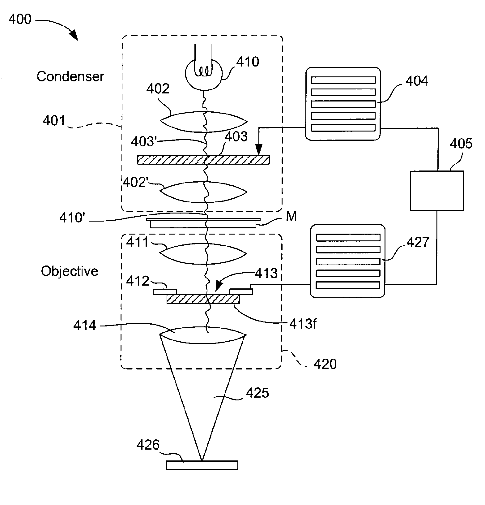
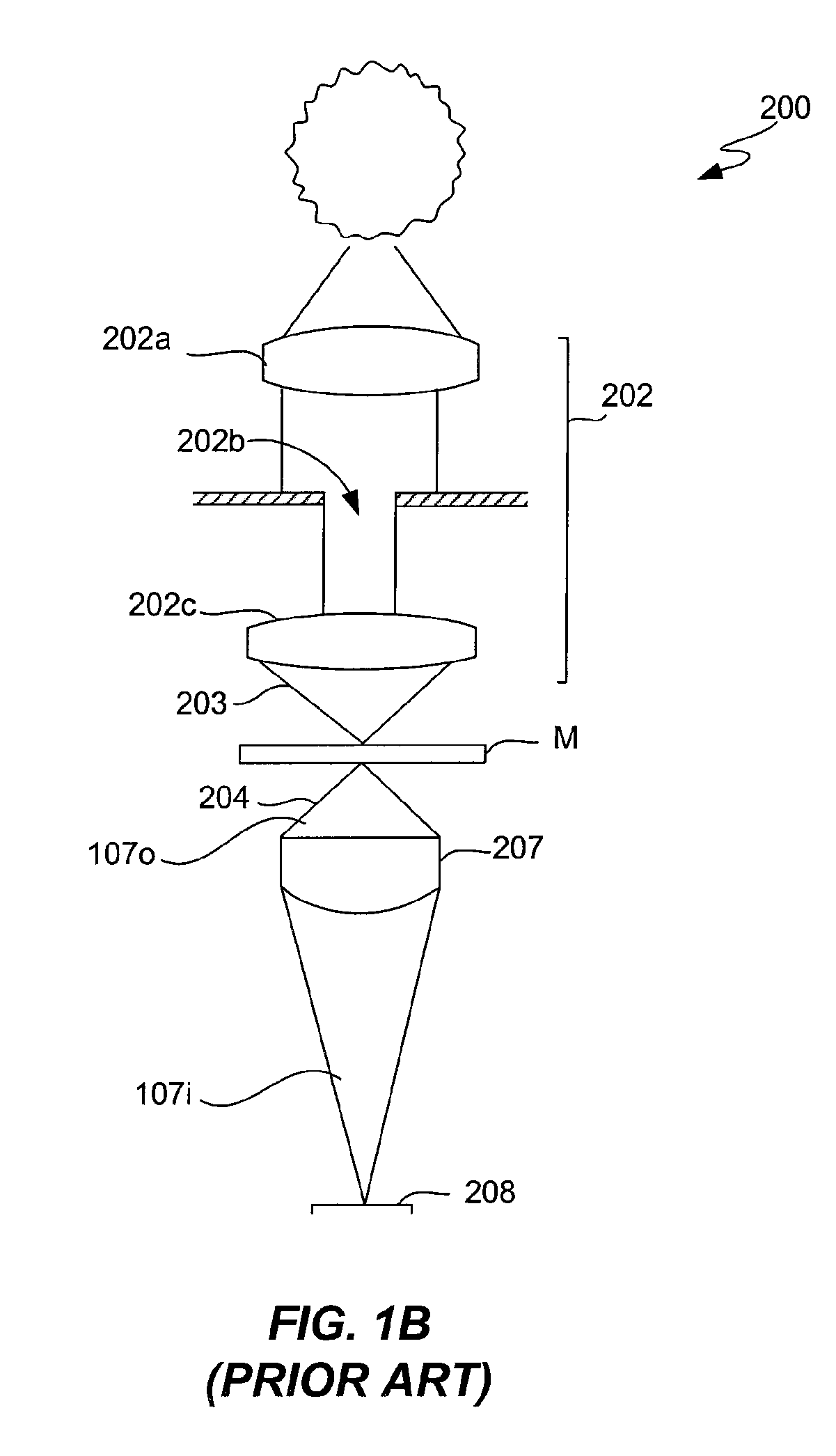
However, such systems have encountered a number of problems. FIG. 2 is an illustration of a common prior art inspection
system 210 embodied in some prior art approaches.
But, such optical parameters are not sufficient to provide the required
magnification to enable inspection.
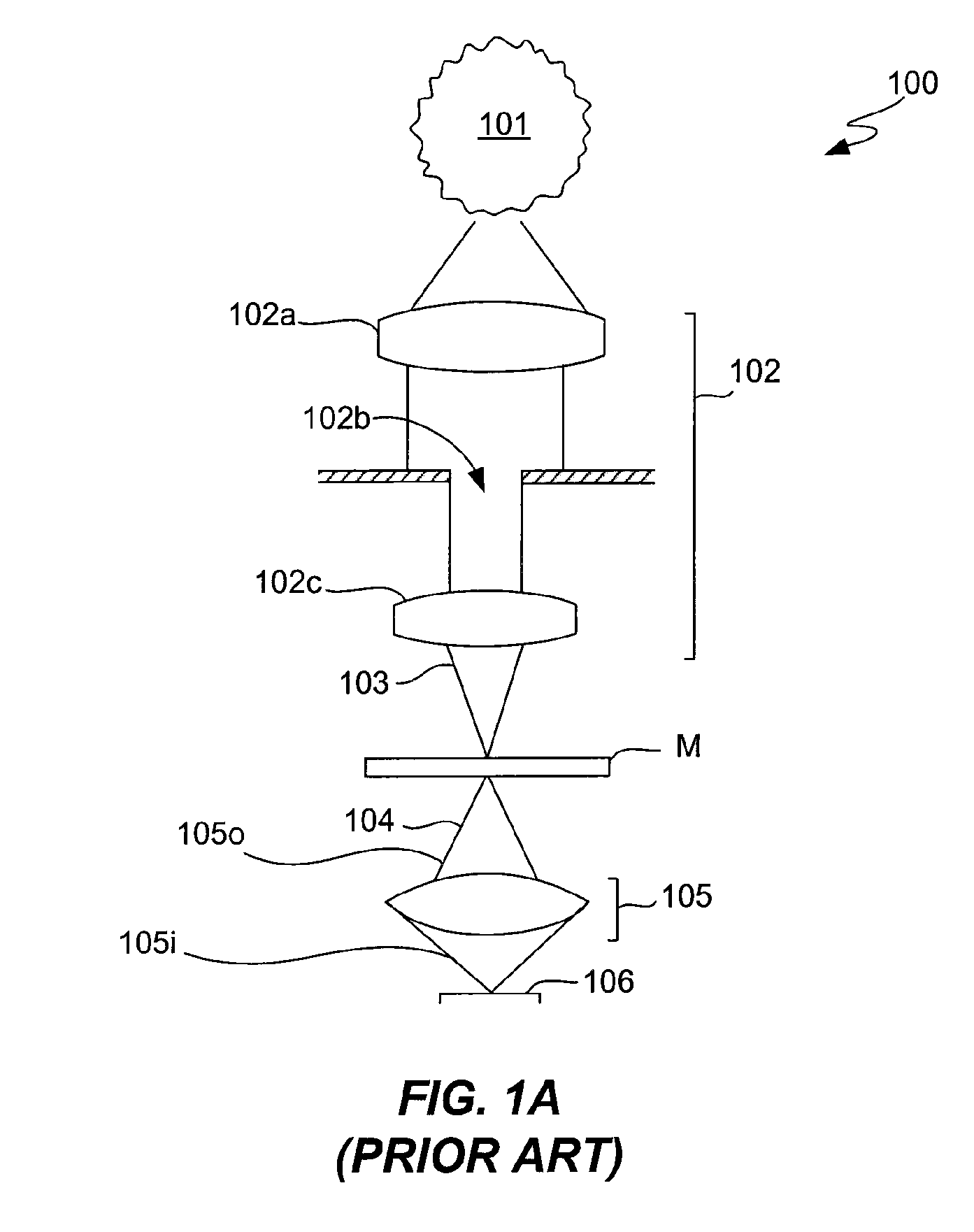
However, as a result of the changes to the optical properties of such systems, these
magnification systems do not accurately model the lithographic properties of the high NA (image NA) systems (e.g., FIG. 1A) used to form patterns of the desired surfaces.
Accordingly, the accuracy of measurements of photolithographic significance has been distorted by the changes in the optical
system to such a degree as to be insufficient for the state-of-art
lithography pattern defect detection.
Thus their usefulness in photomask inspection has been severely limited.
Not surprisingly, the prediction accuracy of such systems is unsatisfactory as the state-of-art
photolithography patterning uses a higher image NA (further enhanced with an immersion liquid) than is used for the AIMS review tool.
The drawback of this approach is that it cannot take compensate for imperfect mask fabrication which is present in almost all cases.
Some drawbacks of this approach include the
low speed at which such e-beam imaging is performed and the high
signal-to-
noise ratio for this method.

