Control device for hybrid vehicle

a control device and hybrid technology, applied in the direction of electric propulsion mounting, instruments, gearing, etc., can solve problems such as engine startup, and achieve the effect of suppressing engine startup

Active Publication Date: 2008-07-24
TOYOTA JIDOSHA KK
View PDF17 Cites 26 Cited by
  • Summary
  • Abstract
  • Description
  • Claims
  • Application Information

AI Technical Summary

Benefits of technology

[0008]The present invention has been completed with the above views in mind and has an object to provide a control device for a hybrid vehicle, hav

Problems solved by technology

In this case, it is likely that engine startup occurs regardless of whether a s

Method used


Image

  • Control device for hybrid vehicle
  • Control device for hybrid vehicle
  • Control device for hybrid vehicle

Examples


embodiment 1

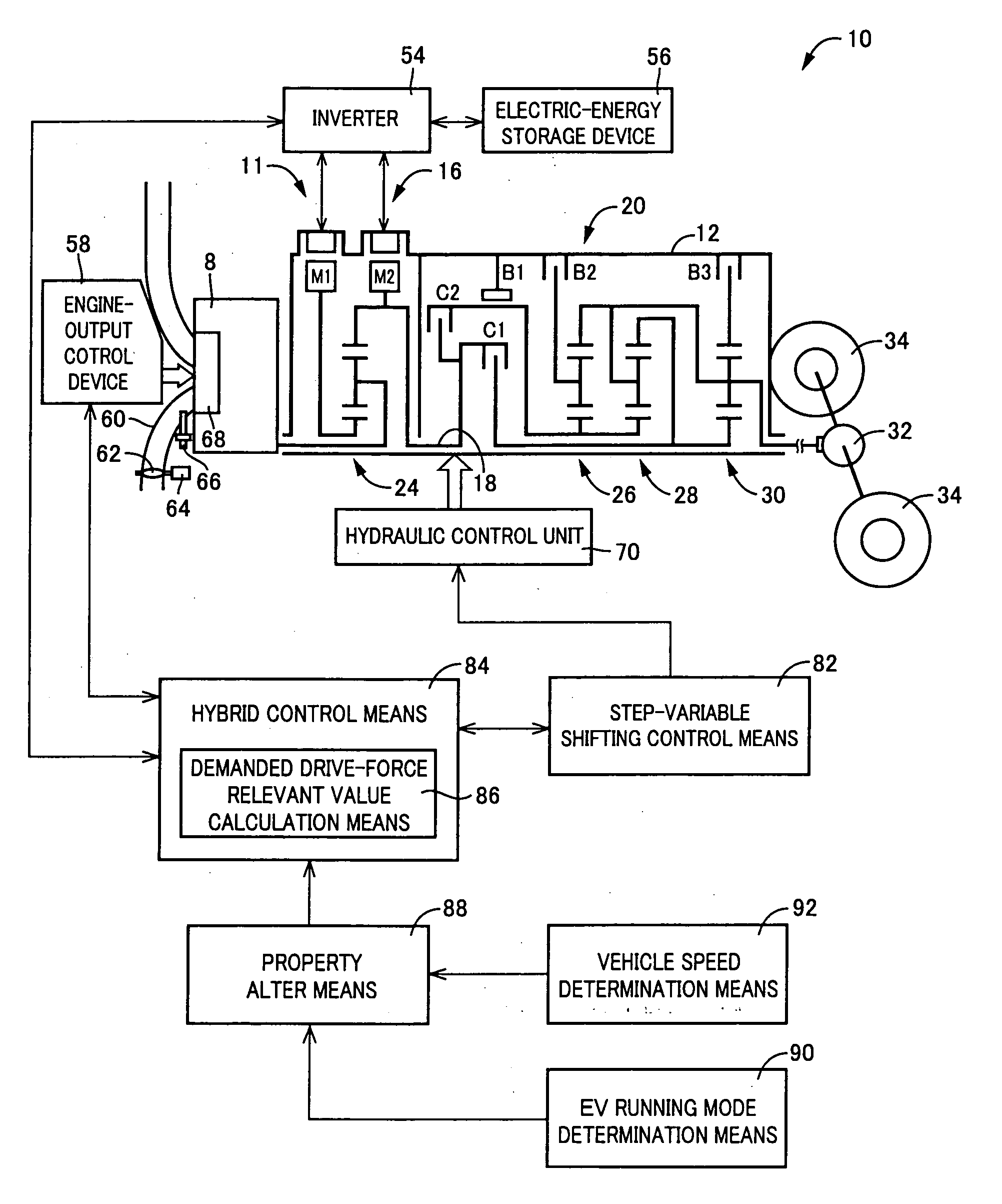
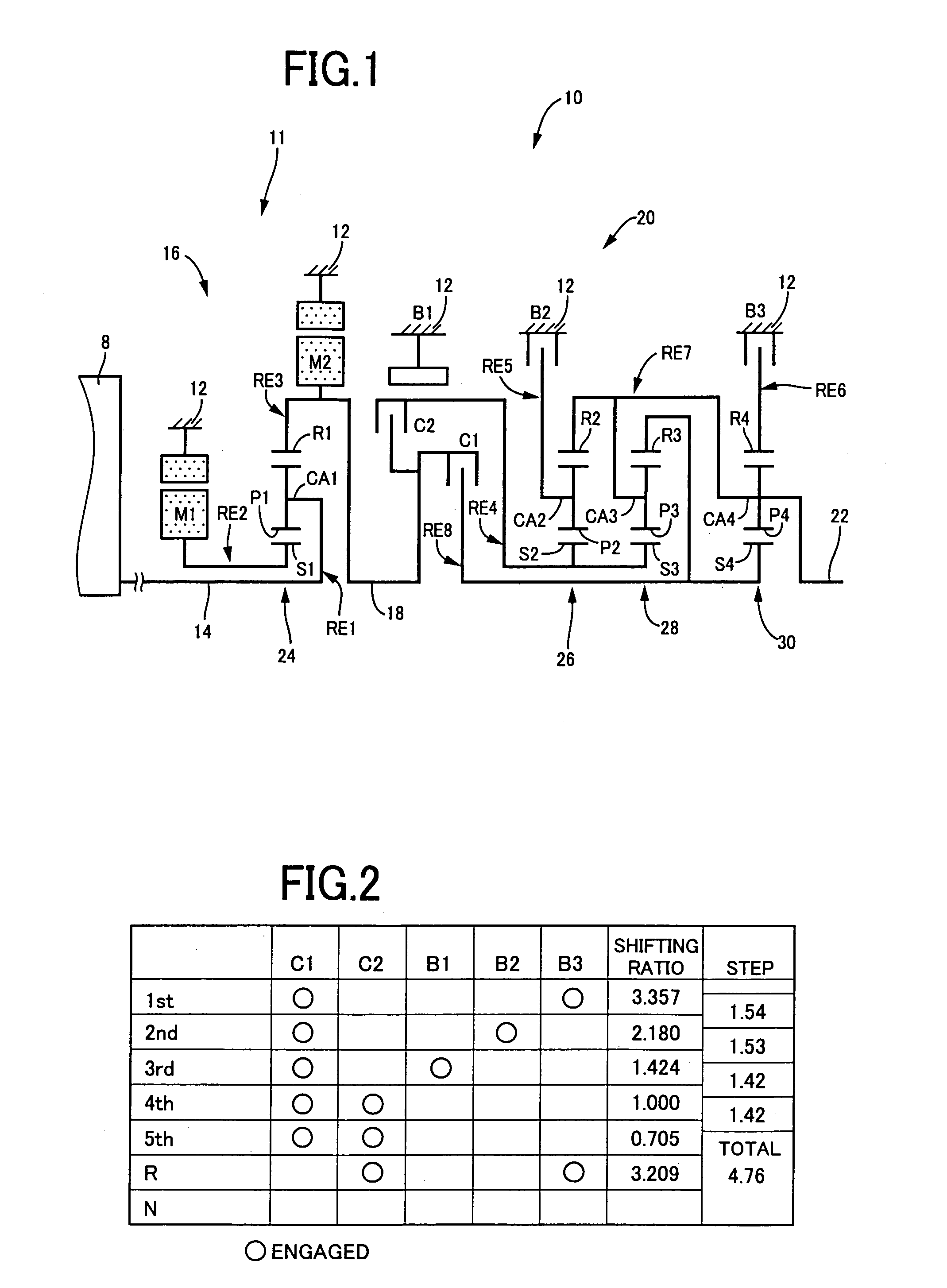
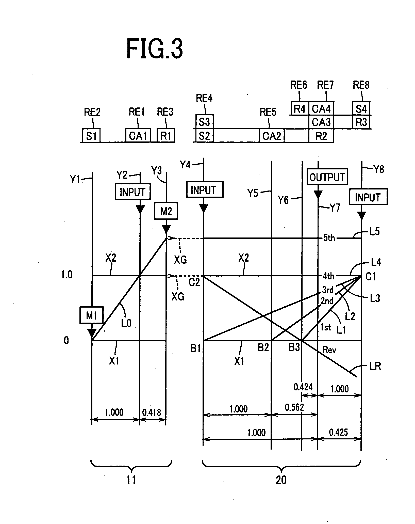
[0037]First embodiment will be explained with reference to FIGS. 1 to 13. FIG. 1 is a skeleton diagram for illustrating a transmission mechanism i.e., shifting mechanism 10 constituting a part of a drive system for a hybrid vehicle to which the present invention is applied. As shown in FIG. 1, the transmission mechanism 10 includes a transmission case 12 (hereinafter referred to as “a case 12”) mounted on a vehicle body as a non-rotary member, an input shaft 14 coaxially disposed inside the case 12 as an input rotary member, an electrically controlled differential portion 11 (hereinafter referred to as a “differential portion 11”) coaxially connected to the input shaft 14 either directly, or indirectly via a pulsation absorbing damper (vibration damping device) not shown, and serving as a continuously variable transmission portion, an automatic transmission portion i.e., shifting portion 20 connected in series in a power transmitting path between the differential portion 11 and driv...

embodiment 2

[0136]Second embodiment will be explained with reference to FIGS. 14 to 16. FIG. 14 is a skeleton view illustrating a structure of a transmission mechanism 100 of another embodiment according to the present invention. FIG. 15 is an engagement operation diagram representing combined operations of hydraulically operated frictional engaging devices for use in shifting operations of the transmission mechanism 100. FIG. 16 is a collinear chart illustrating the shifting operations of the transmission mechanism 100.

[0137]Like the first embodiment, the transmission mechanism 100 includes the differential portion 11 comprised of the first electric motor M1, the power transmitting mechanism 16 and the second electric motor M2, and a forward-drive three-stage automatic transmission portion 102 connected between the differential portion 11 and the output shaft 22 in series via the power transmitting member 18. The power transmitting mechanism 16 includes the single-pinion type first planetary g...


PUM


Abstract

A control device for hybrid vehicle is provided with property alter means 88 that is operative based on whether or not an EV running mode is set and alters a given property used for determining demanded output torque TOUTt of a transmission mechanism 10 by referring to an accelerator opening Acc. This suppresses occurrence of engine startup to meet a requirement for the EV running mode to be initiated. The property alter means 88 alters the given property such that during an EV running mode turn-on state, demanded output torque TOUTt determined based on the accelerator opening Acc has a lower value than that set for an EV running mode turn-off state. That is, this causes a drop in sensitivity of demanded output torque TOUTt determined based on the accelerator opening Acc. Thus, the occurrence of engine startup induced upon depressive operation of an accelerator pedal during the EV running mode is suppressed.

Description

BACKGROUND OF THE INVENTION[0001]1. Field of the Invention[0002]This invention relates to control device for hybrid vehicle, having an engine and an electric motor, and, more particularly, to a control device for hybrid vehicle for effectuating switching between a motor running mode and an engine running mode.[0003]2. Description of the Related Art[0004]A control device for a hybrid vehicle has heretofore been well known as including an engine and electric motor that enable the switching between a motor running mode relaying on a drive-power source composed of only the electric motor, and engine running mode relaying on another drive-power source mainly composed of the engine.[0005]For instance, Patent Publication 1 (Japanese Patent Application Publication No. 2005-304201) discloses a hybrid vehicle having a control device of such a structure described above. Patent Publication 1 discloses a technology in which the drive-power source includes the engine and electric motor and an EV-...

Claims


Application Information

Patent Timeline
IPC IPC(8): B60W20/00B60W10/04B60K6/445B60K6/547B60L50/16B60W10/08
CPCB60K1/02B60K6/365B60K6/445B60K6/547B60W2540/04F16H3/728Y02T10/6239F16H2200/0043F16H2200/0047F16H2200/201F16H2200/2012F16H2200/2041F16H2200/2043F16H2037/0873B60W2540/215Y02T10/62B60W50/082B60W50/085
Inventor KUMAZAKI, KENTAMATSUBARA, TOORUTABATA, ATSUSHI
Owner TOYOTA JIDOSHA KK
Why Eureka
Try Eureka