
Method and device for protective switching of pseudo-wires on packet switching network

a packet switching network and protective switch technology, applied in the field of communication, can solve the problems of low switching efficiency, wrong switching of some good working pws, and simultaneous switching of all of the pws, so as to avoid repeating oscillation of protective switching, avoid heavy burden on the system, and improve switching efficiency

Inactive Publication Date: 2008-07-24
HUAWEI TECH CO LTD
View PDF9 Cites 25 Cited by
  • Summary
  • Abstract
  • Description
  • Claims
  • Application Information

AI Technical Summary

Benefits of technology

[0029]It can be seen from the above technical solutions provided by the present invention that, through the grouping of PWs according to a criterion, such as the same source and destination, the same path, the same type and the same QoS requirement, one-to-one mapping is established between the PWs in the working PWG and the PWs in the protective PWG; when a fault occurs in the working PWG, the services on the working PWG can be switched onto the protective PWG. The protective switching is performed only for a desired group, thereby enabling the edge-to-edge grouped protective switching of the PWs on the PSN, so that the problem of edge-to-edge protective switching of PWs on an existing PSN is solved.
[0030]As mentioned above, the protective switching operation according to an embodiment of the invention is determined according to the monitoring results, and the protective switching is performed only for the PWG in which the protective switching condition is met. As a result, the simultaneous switching of all of the PWs within a tunnel due to one failed PW can be avoided and the switching efficiency can be improved. Also, the wrong switching of normal PWs and repeating oscillation of the protective switching are avoided.
[0031]Further, the system need not monitor each working PW and each protective PW, therefore avoiding laying a heavy burden on the system and degrading the system performance. As a result, the switching speed will be increased and the switching time will not exceed the maximum switching time allowed by the communications network. Therefore, the QoS is improved.

Problems solved by technology

However, the PW protection standard is not defined in standards organizations, such as IETF PWE WG, ITU-T, Metro Ethernet Forum (MEF) and Multiprotocol Label Switching / Frame Relay / Asynchronous Transfer Mode Alliance (MFA).
In this case, one failed PW will result in the simultaneous switching of all of the PWs within the segment of the tunnel.
As a result, the switching efficiency is not high, and the switching of some good working PWs may be wrongly performed.
If a fault occurs in protective connections for a certain PW, which cannot be isolated from other PWs by the protective switching, it results in the interruption of the services on the PW and the repeating fluctuation during the protective process of the PW, even network paralysis.
If the method is adopted, the system is required to monitor each of the PWs, thereby laying a heavy burden on the system and degrading the system performance.

Method used


Image

  • Method and device for protective switching of pseudo-wires on packet switching network
  • Method and device for protective switching of pseudo-wires on packet switching network
  • Method and device for protective switching of pseudo-wires on packet switching network

Examples


Embodiment Construction

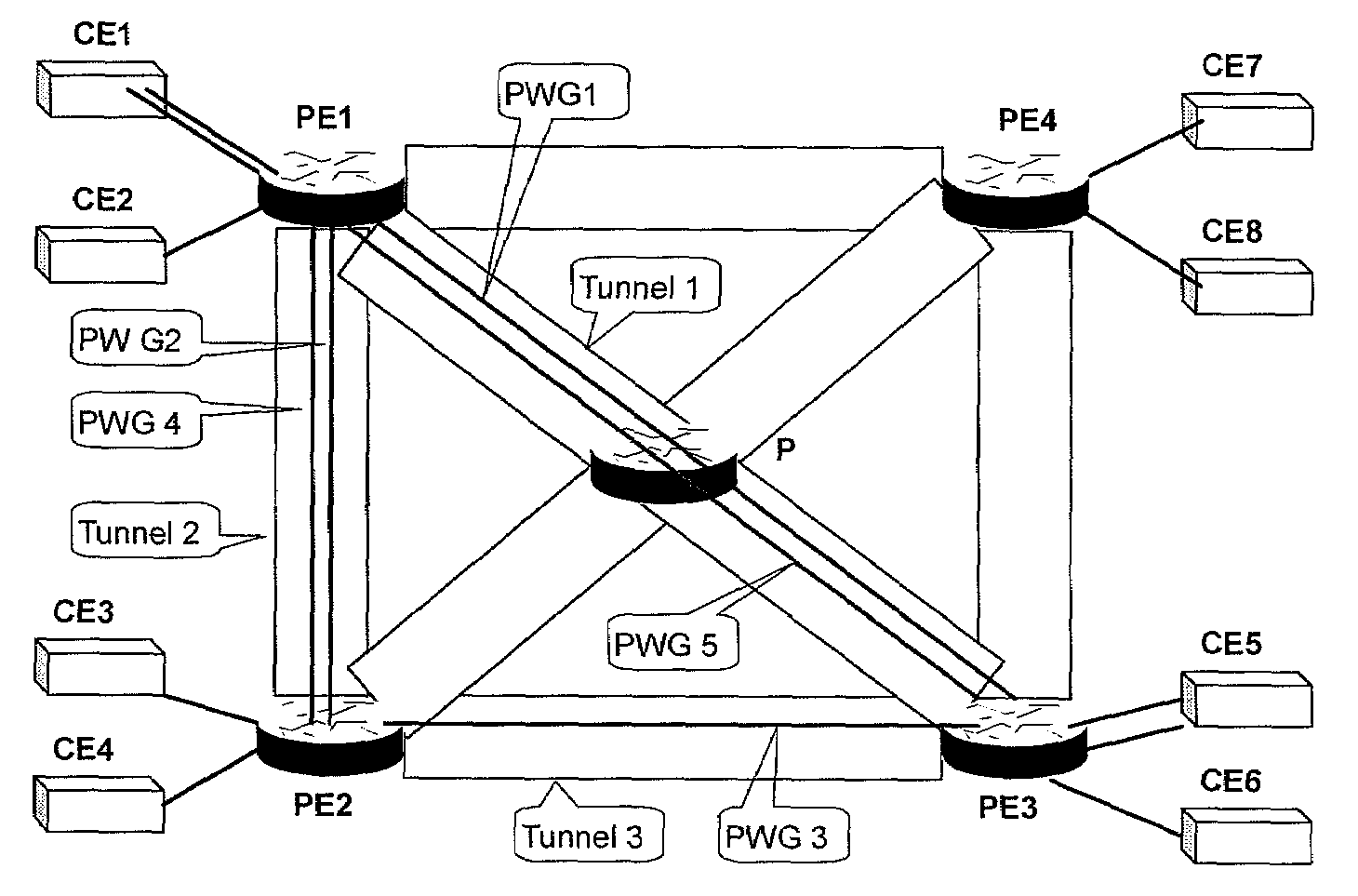
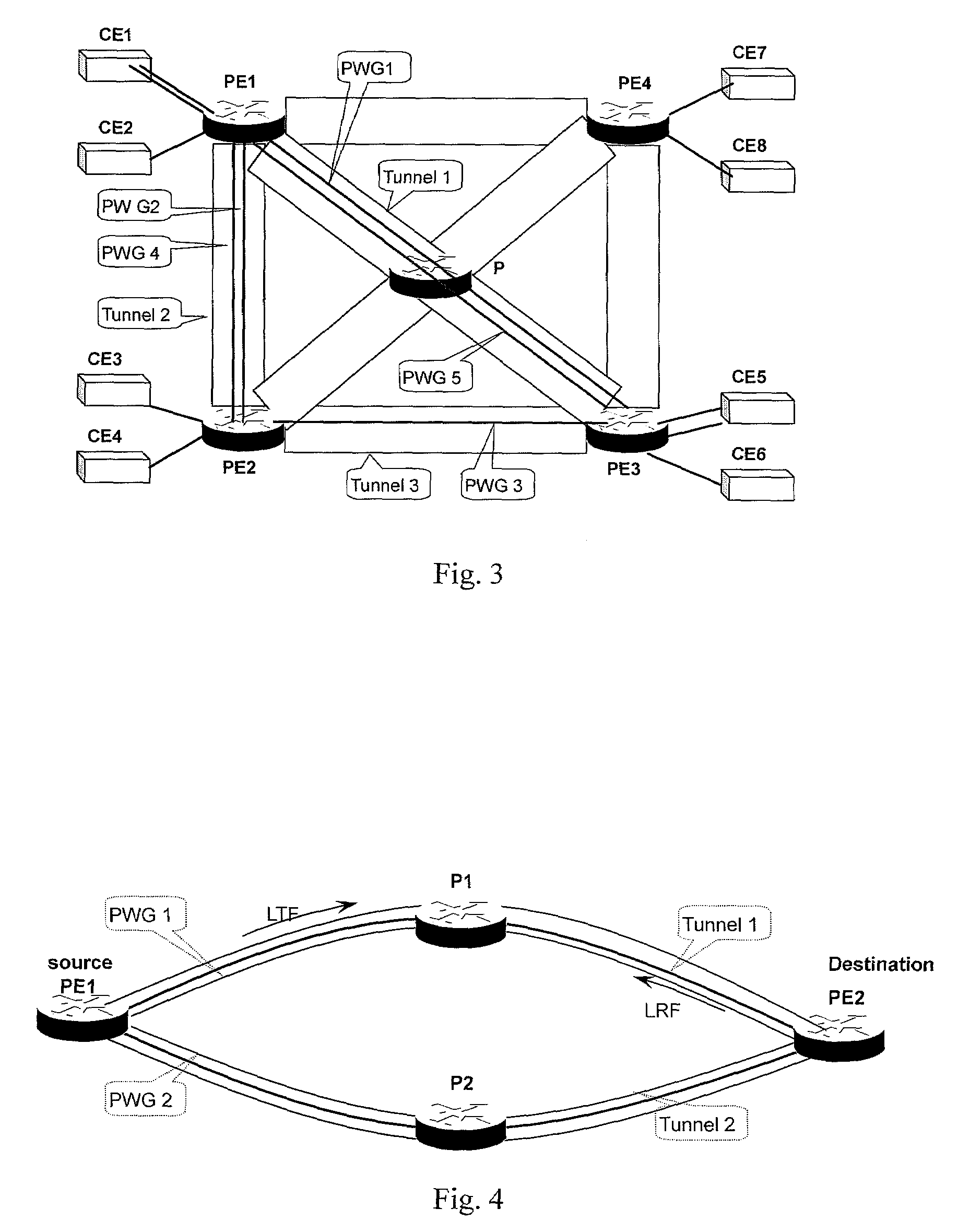
[0036]The present invention is the grouping of PWs on a PSN to establish one-to-one mapping between the working PWG and the protective PWG, monitoring the state of a typical PW in the working PWG and the state of the corresponding protective PW in the protective PWG, and switching the services on the working PWG onto the protective PWG when a fault occurs in the working PWG but the protective PWG is in a normal state.

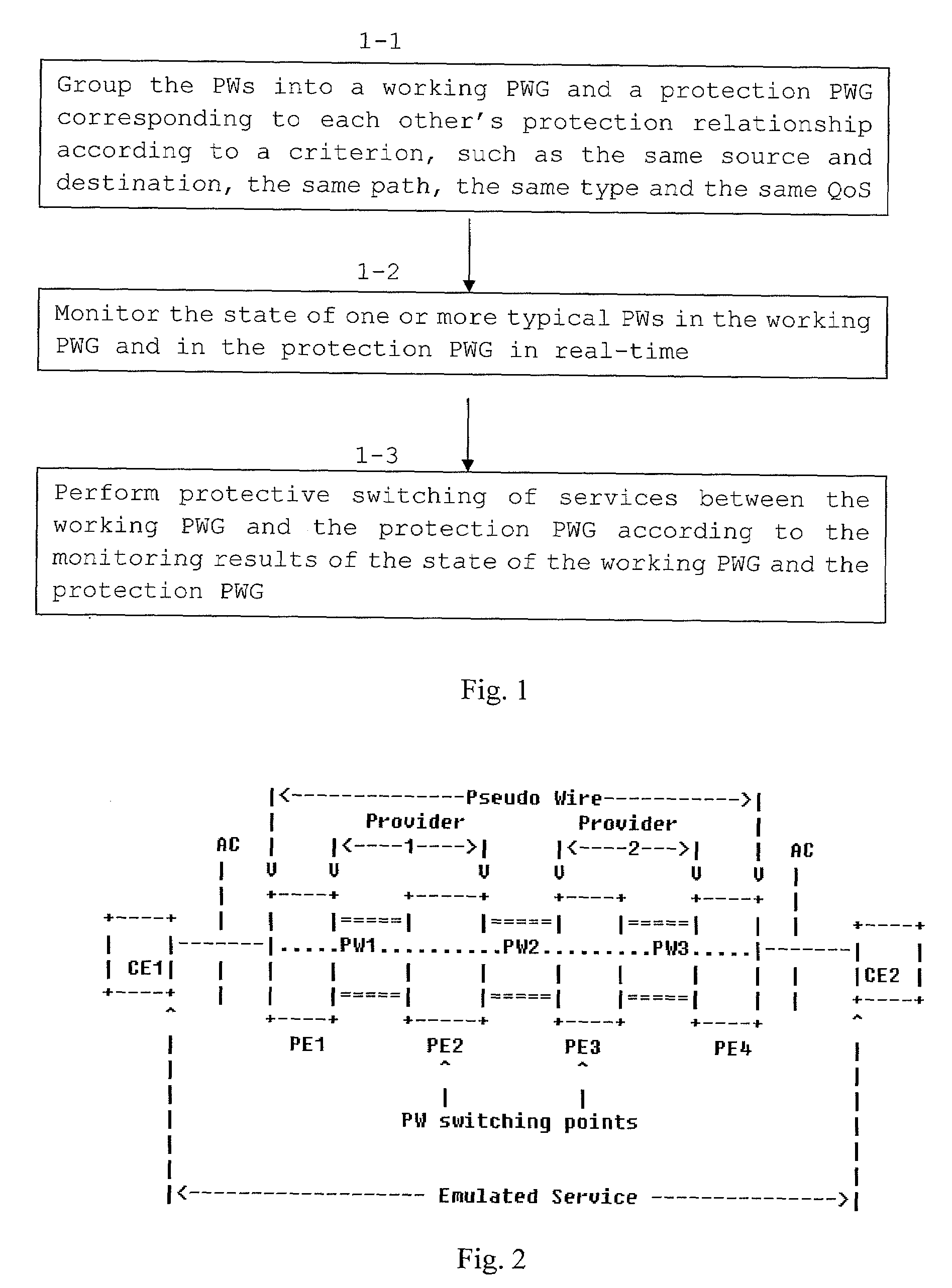
[0037]The present invention is now described in detail in conjunction with the accompanying drawings. A processing flowchart according to a particular embodiment of the method of the present invention is shown in FIG. 1, in which:

[0038]In block 1-1, PWs are grouped into a working PWG and a protective PWG corresponding to each other according to a preset criterion, such as the same source and destination, the same path, the same type, or the same QoS requirement.

[0039]According to an embodiment of the invention, first of all, the PWs on the PSN are required to be grouped...


PUM


Abstract

The present invention provides a method and device for protective switching of pseudo-wires on a Packet Switching Network. The method includes grouping the pseudo-wires on the Packet Switching Network into a working pseudo-wire group and a protective pseudo-Wire group corresponding to each other's relationship of protection; performing on services the protective switching between the working pseudo-wire group and the protective pseudo-wire group according to the state of the working pseudo-wire group and protective pseudo-wire group. The method of the present invention can be used to perform edge-to-edge grouped protective switching of the pseudo-wires on the Packet Switching Network.

Description

CROSS-REFERENCE TO RELATED APPLICATIONS [0001]The present application is a continuation of PCT Application No. PCT / CN2006 / 001349, filed on Jun. 15, 2006, which claims priority to Chinese Patent Application No. 200510107438.0, filed on Sep. 30, 2005. All of these applications are incorporated herein by reference for all purposes.FIELD OF THE INVENTION [0002]The present invention relates to the field of communications, and more particularly, to a method and device for protective switching of pseudo-wires (PWs) on a Packet Switching Network (PSN).BACKGROUND OF THE INVENTION [0003]Several standards for Pseudo-Wire Emulation were defined in the Internet Engineering Task Force Pseudo-Wire Emulation Edge-to-Edge working group (IETF PWE3 WG). According to the principle of the PWE3, an edge-to-edge tunnel is created for transporting various original Layer 1 and Layer 2 services, which include Asynchronous Transfer Mode (ATM), Ethernet, Frame Relay, High level Data Link Control (HDLC) / Peer-to...

Claims


Application Information

Patent Timeline
IPC IPC(8): H04L12/56
CPCH04L45/10H04L45/28H04L45/22
Inventor LI, XIXIANG
Owner HUAWEI TECH CO LTD
Learn More