Steam turbine

a steam turbine and steam technology, applied in the direction of machines/engines, stators, liquid fuel engines, etc., can solve the problems of high maintenance costs, damage to seal strips, and inability to set up the clearance between the rotation part and the static part to the minimum, so as to improve the efficiency of steam turbines and maintainability. high, the effect of reducing leakag

Active Publication Date: 2008-07-24
KK TOSHIBA
View PDF10 Cites 19 Cited by
  • Summary
  • Abstract
  • Description
  • Claims
  • Application Information

AI Technical Summary

Benefits of technology

[0012]In view of the above-identified circumstances, it is therefore an object of the present invention to provide a seal structure for moving blade tips in which the maintainability is high even if the seal strips come into contact with the abradable layer to damage the abradable layer, and the leakage flow is reduced by preventing the abradable layer from being cut more than necessary, thereby making it possible to improve the efficiency of the steam turbine.

Problems solved by technology

In the steam turbine, since the rotor and casing are heated to be deformed in the transient operation at the time of the start up and shut down, it is impossible to set up the clearance between the rotation part and the static part to the minimum by only taking the rated operation time into consideration.
Furthermore, in case a contact is raised between the rotation part and the static part during the operation, the seal strips may be damaged due to the contact.
In some cases, the seal strips may be seriously damaged.
Accordingly, when seal fins come into contact with the abradable layer, especially in the transient state of the turbine at the times of starts and stops, there is raised an unstable behavior in which the seal support member segments jounce in the radial direction, which may raise a possibility that the seal fins and the abradable layer come into contact with each other widely and sometimes deeply.
In this way, when the seal strips and the abradable layer come into contact with each other, there is a problem that, in the steady operation, the clearance at this part becomes large to increase the leak steam amount, and, furthermore, depending on the way of contact, the seal strips and abradable layer may be damaged.
Furthermore, under the seal structure of the conventional technique, since the seal support member segments are engaged with the nozzle diaphragm outer ring via springs such that the seal support member segments can shift in the radial direction, there is a disadvantage that, so as to keep the structural intensity of the nozzle diaphragm outer ring sufficiently, the nozzle diaphragm outer ring becomes large.
However, in the configuration shown in FIG. 9, since the nozzle diaphragm outer ring 3a of the respective stages having the abradable layer arranged on the inner circumference surface thereof is coupled by the bolts 9 to be unitedly formed, in case the seal strips 4d of a stage come into contact with the abradable layer 3d to damage the abradable layer 3d, the abradable layer 3d has to be repaired after detaching the entire nozzle diaphragm 3 of the stage, which raises another problem of making it difficult to repair the seal structure.

Method used


Image

  • Steam turbine
  • Steam turbine
  • Steam turbine

Examples


Embodiment Construction

[0024]Now, preferred embodiments of the present invention will be described by referring to the accompanying drawings.

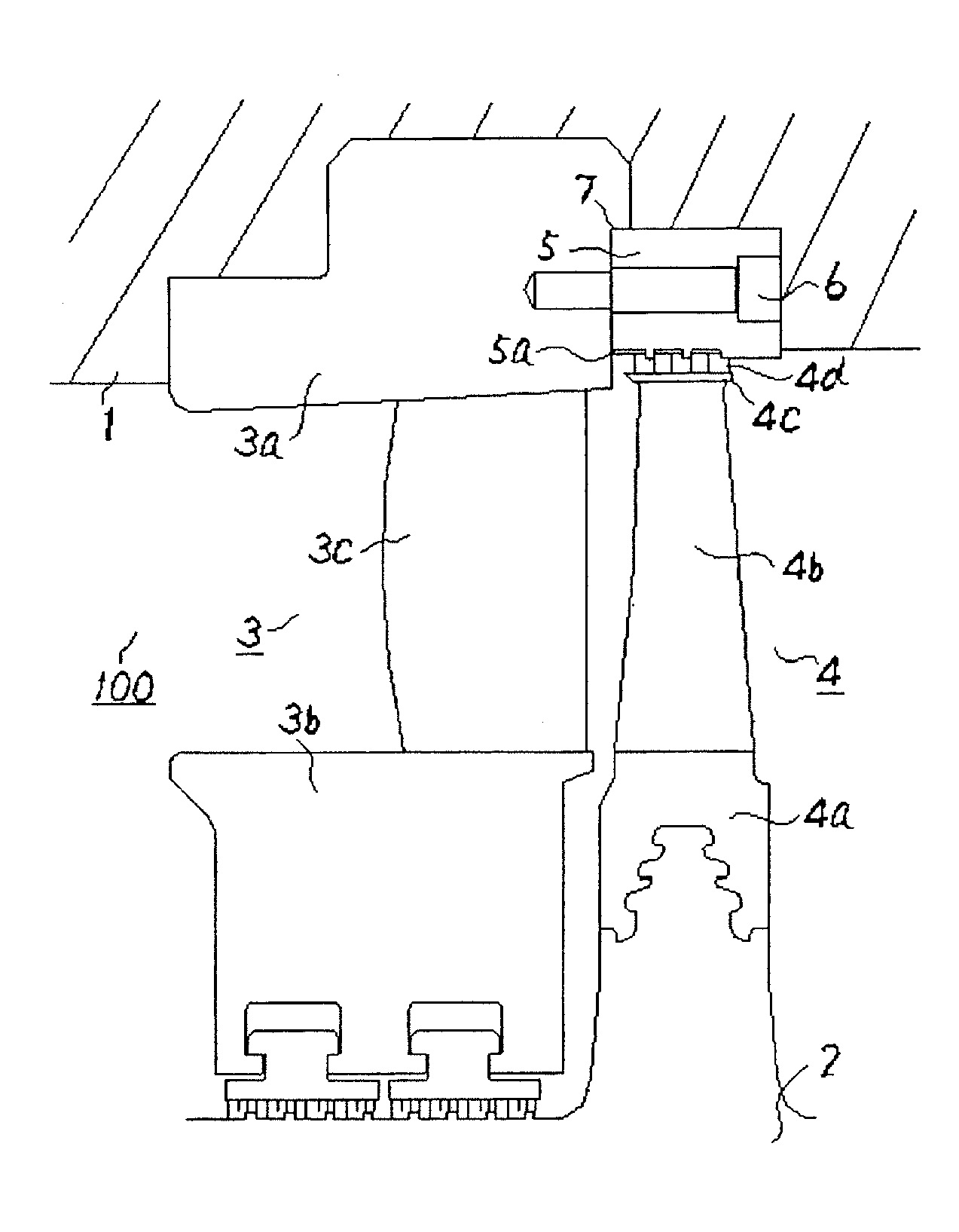
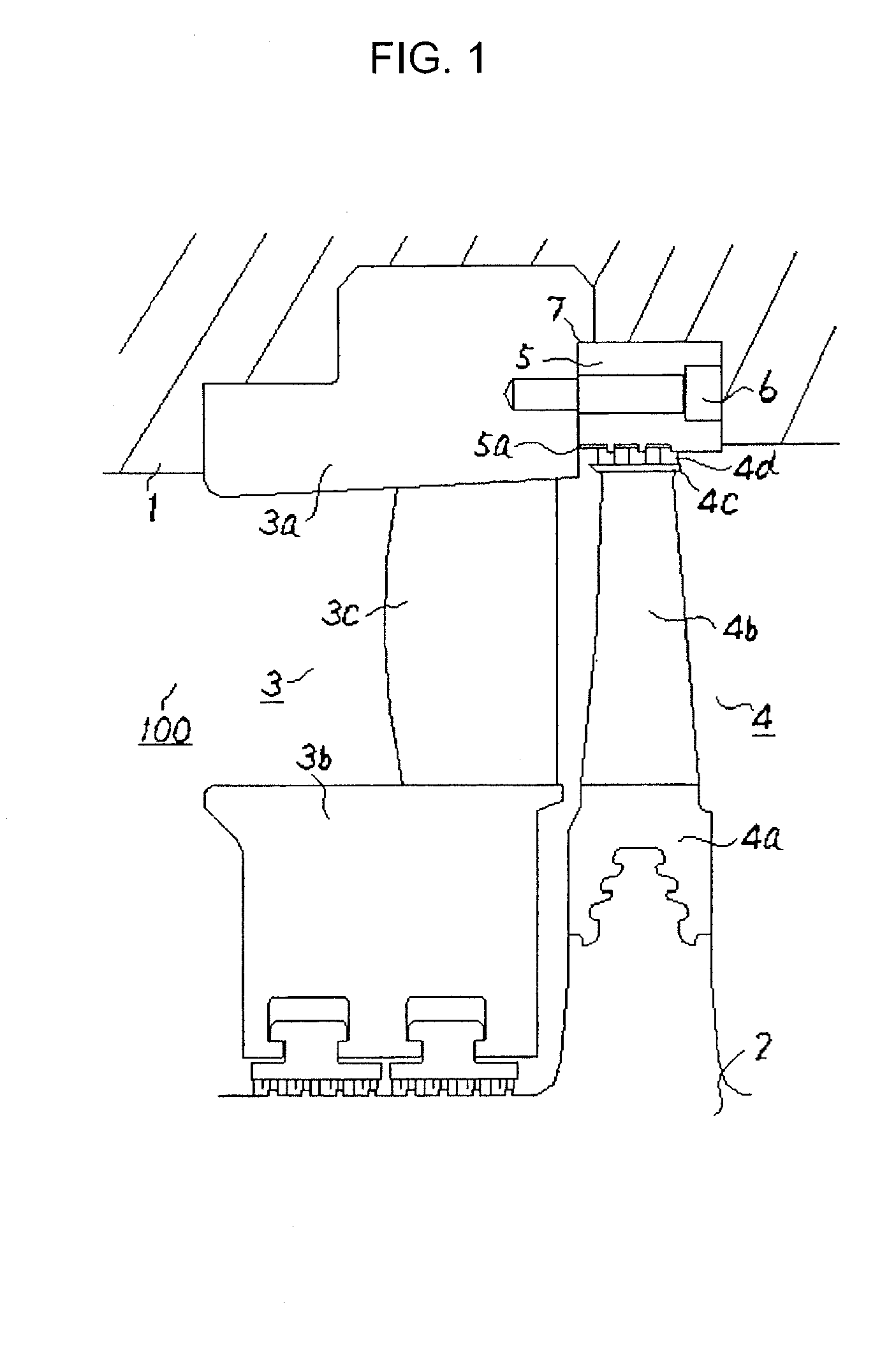
[0025]FIG. 1 shows a meridional sectional view showing a meridional plane being a cross section including the rotation axis of a stage of a steam turbine according to a first embodiment of the present invention.

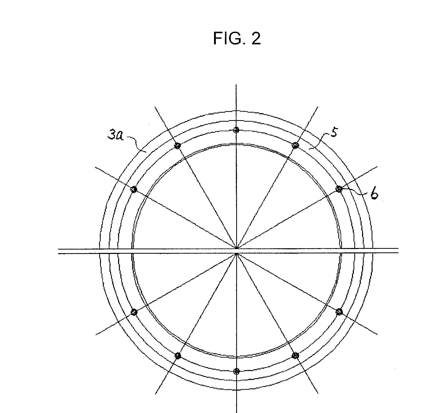
[0026]A steam turbine 100 has a rotor2 which is rotatably arranged in a casing 1. The rotor 2 is made to rotate by steam which is working fluid. In the casing 1, nozzle diaphragms 3 are fixed to form a static part similarly to the casing 1. Each of the nozzle diaphragms 3 has a plurality of nozzle blades 3c. The nozzle blades 3c are arranged in the steam path formed between a nozzle diaphragm outer ring 3a and a nozzle diaphragm inner ring 3b, and are arranged in the circumferential direction. The nozzle diaphragm outer ring 3a is fixed to the casing 1, and is substantially concentrically arranged with respect to the rotor 2.

[0027]On the outer circumference pa...


PUM


Abstract

A steam turbine has: a casing; a rotor rotatably arranged in the casing; a nozzle diaphragm concentrically arranged with respect to the rotor, the nozzle diaphragm being engaged with the casing; moving blades arranged in circumferential direction on outer circumference of the rotor at positions adjacent to the nozzle diaphragm; seal strips circumferentially extending on tips of the moving blades, the seal strips protruding in radial outward direction; and an abradable structure rigidly connected to the nozzle diaphragm. The abradable structure faces the seal strips in radial direction at a facing surface, and has an abradable part made of an abradable material arranged at the facing surface.

Description

CROSS REFERENCES TO RELATED APPLICATIONS[0001]The present invention contains subject matter related to Japanese Patent Application No. 2007-001325, filed in the Japanese Patent Office on Jan. 9, 2007, the entire content of which is incorporated herein by reference.BACKGROUND OF THE INVENTION[0002]This invention relates to a steam turbine, and more particularly, to a leakage prevention structure for working fluid which is arranged on moving blade tip.[0003]FIG. 9 shows a general steam turbine. A steam turbine 100 has a rotor 2 which is rotatably arranged in a casing 1. The rotor 2 is made to rotate by steam which is working fluid. In the casing 1, nozzle diaphragms 3 are fixed to form static parts together with the casing 1. Each of the nozzle diaphragms 3 has a plurality of nozzle blades 3c which are arranged in the steam path formed between a nozzle diaphragm outer ring 3a and a nozzle diaphragm inner ring 3b, which are annular members, and are arranged in the circumferential direc...

Claims


Application Information

Patent Timeline
Patent Type & Authority Applications(United States)
IPC IPC(8): F01D11/12
CPCF01D5/3046F01D11/001F01D11/02F05D2220/31F01D25/246F05D2240/55F01D11/122
Inventor IKEDA, KAZUTAKASASAKI, TAKASHIASAI, SATORUSAKAKIDA, HITOSHIKAMIMURA, KENJIOGINO, RYOHEIOOISHI, YASUSHI
Owner KK TOSHIBA
Why Eureka
Try Eureka