Instrumentation for knee surgery

a knee surgery and instrumentation technology, applied in the field of instruments, can solve the problems of poor joint performance, patient discomfort, inconvenient operation, etc., and achieve the effects of increasing visibility, equal tensioning, and quick and easy operation

Inactive Publication Date: 2008-07-24
MCMINN DEREK JAMES WALLACE
View PDF20 Cites 59 Cited by
  • Summary
  • Abstract
  • Description
  • Claims
  • Application Information

AI Technical Summary

Benefits of technology

[0036]An advantage of the fifth aspect of the present invention is that only a single distraction device is required to alter the tension of both the medial and lateral collateral ligaments and so the procedure can be performed quickly and easily with increased visibility and access to the knee during the operation. Importantly, the present invention allows for equal tensioning of the medial and lateral collateral ligaments and soft tissue structures on either side of the knee since the angle of the femur relative to the tibia is not fixed during the distraction procedure and so with the distraction device positioned centrally of the tibia the angle of the femur should naturally adjust to ensure the collateral ligaments are equally tensioned. The present invention allows for better control in s...

Problems solved by technology

Mal-alignment of the cutting guide in either of these capacities will lead to incorrect location of the femoral component.
This may lead to patient discomfort and poor performance of the joint.
If the cutting guide is located too far in the posterior direction, the cuts will result in a divot or notch in the femur, which may lead to supracondylar fracture of the femur.
Furthermore, if the cutting-guide, and therefore the femoral component, is rotationally mal-aligned, the collateral ligaments may not be under the correct tension.
If these ligaments and structures are not under equal tension the patient will have a feeling of instability and there is an increased risk that the bearing parts of the TKR will dislocate.
Such distraction devices are usually employed in spinal surgery and are large, heavy and cumbersome devices.
Since they are operate...

Method used


Image

  • Instrumentation for knee surgery
  • Instrumentation for knee surgery
  • Instrumentation for knee surgery

Examples


Embodiment Construction

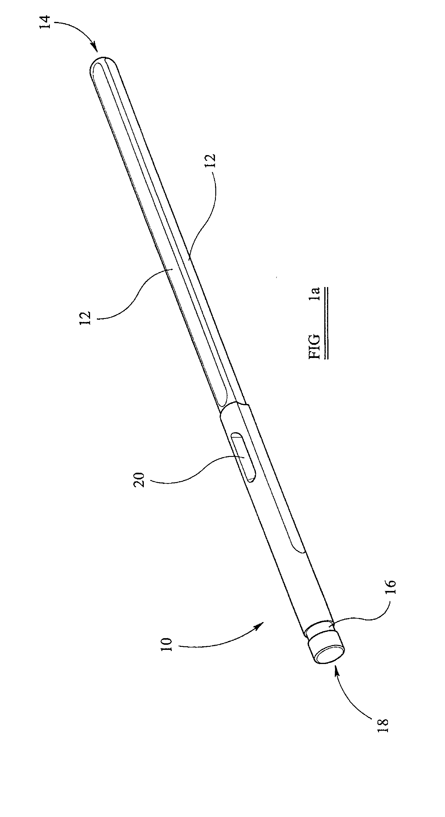
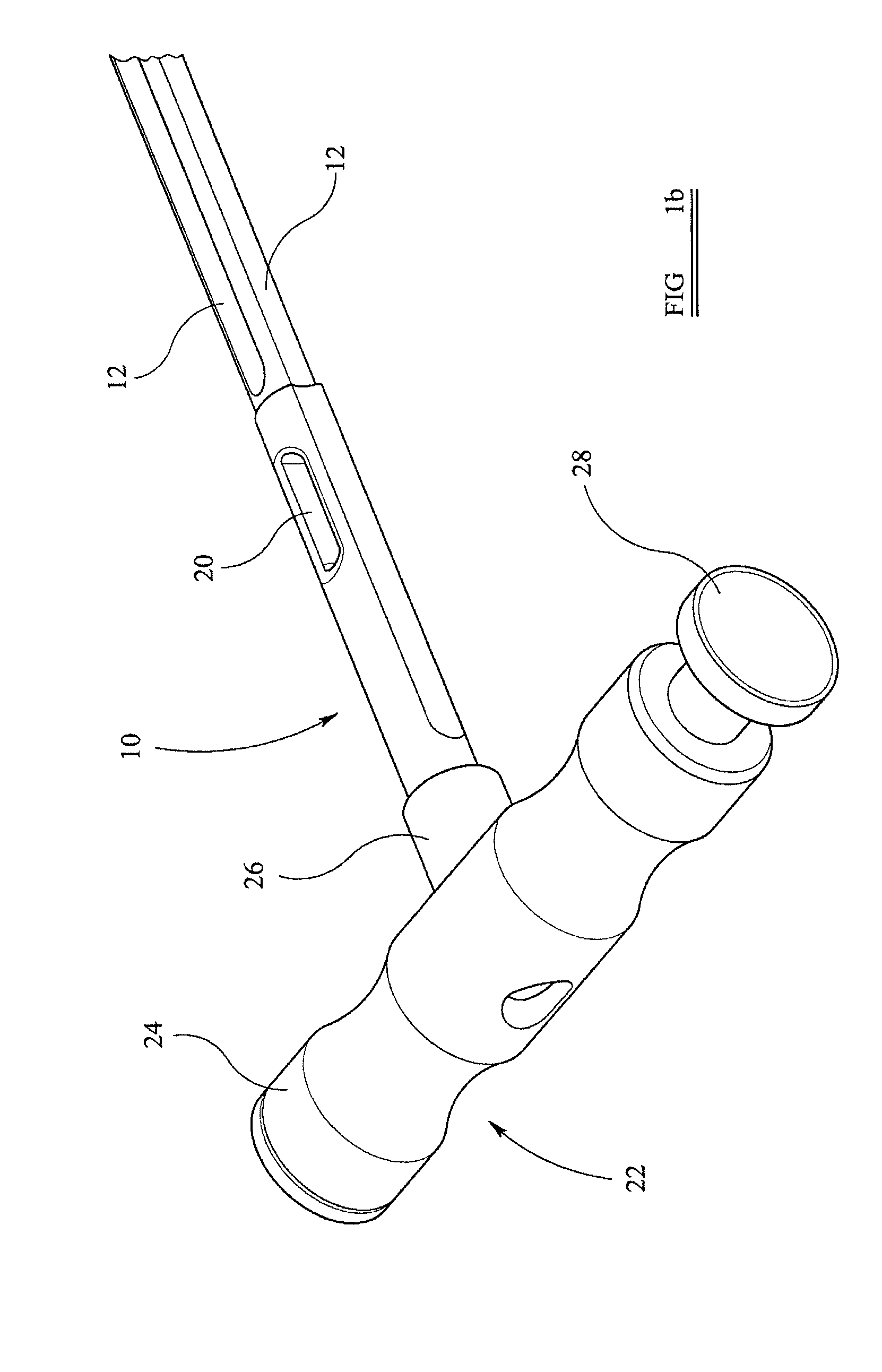
[0063]With reference to FIG. 1a, there is illustrated an intramedullary rod 10 according to the present invention. The rod 10 is made from metal and is substantially cylindrical. Four equi-spaced longitudinal grooves 12 extend along the rod 10 from a first end 14. An annular groove 16 is provided a short distance from a second end 18 of the rod 10. An aperture 20 is provided approximately a third of the way along the length of the rod 10 from the second end 18. The aperture 20 passes orthogonally through the longitudinal axis of the rod 10. The aperture 20 has a width substantially equal to the width of the longitudinal grooves 12 and is disposed such that it is aligned with a respective longitudinal groove 12 on either side of the rod 10. The aperture 20 has a length substantially greater than its width so as to form an elongate slot. The two longitudinal grooves 12 that are aligned with the aperture 20 terminate close to it while the other two longitudinal grooves 12 extend to a p...


PUM


Abstract

Instrumentation for use in knee surgery comprises an intramedullary rod (10) for insertion into an end of a femur (100) and a distraction device (62) coupleable to the intramedullary rod (10) and operable between the intramedullary rod (10) and the tibia for adjusting the tension of the collateral ligaments on either side of the knee. A cutting guide (70) is configured to locate over an intramedullary rod (10) that has been inserted into an end of a femur (100), such that the position of the cutting guide (70) relative to the intramedullary rod (10), and therefore the femur (100), is adjustable in at least the anterior-posterior direction. A kit for use in knee surgery is provided and a method of adjusting the tension of the collateral ligaments on either side of a knee is taught.

Description

FIELD OF THE INVENTION[0001]This invention relates to instrumentation for use in knee surgery. Particularly, but not exclusively, the invention relates to instrumentation for use in total knee replacement (TKR) operations.BACKGROUND TO THE INVENTION[0002]Prosthetic knee replacement surgery is employed to replace damaged or diseased parts of the knee. A particularly common disease that affects joints such as the knee is osteoarthritis. This disease usually increases in severity with age and leads to a high demand for successful knee replacement operations.[0003]So-called total knee replacement (TKR) surgery involves replacing the ends of the femur and tibia with prosthetic femoral and tibial components. In some cases, the patella is also replaced with a patella component. During surgery, the patient's femur and tibia are resected, using appropriate cutting instruments, to the form required for mating with the respective femoral and tibial components.[0004]The tibial component of a kn...

Claims


Application Information

Patent Timeline
IPC IPC(8): A61B17/58
CPCA61B2017/0268A61B17/155A61B17/025A61F2/389
Inventor MCMINN, DEREK JAMES WALLACE
Owner MCMINN DEREK JAMES WALLACE
Why Eureka
Try Eureka